
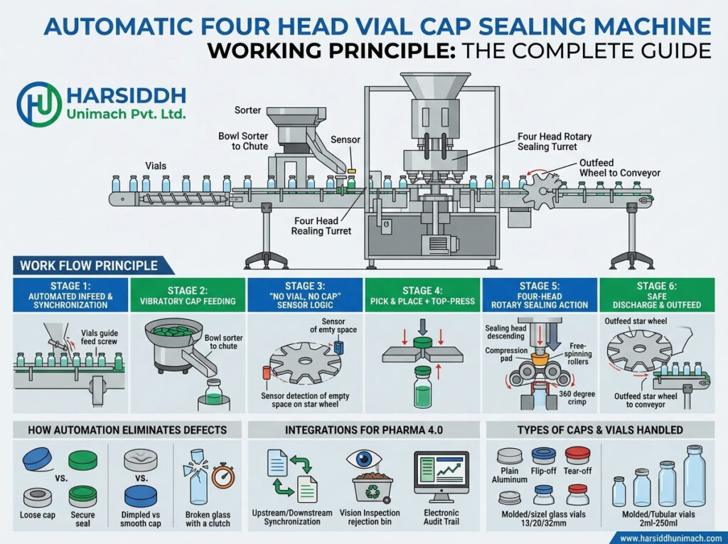
After a vial is filled and stoppered, one final mechanical step secures everything in place: crimping an aluminium seal over the rubber stopper. This seal holds the stopper firmly against the vial lip, maintains container closure integrity throughout shelf life and provides clear tamper evidence through its flip-off cap.
The automatic four head vial cap sealing machine is one of the most widely used machines for this job. It combines continuous rotary motion with four sealing heads working in sequence, delivering consistent crimps at a speed that suits small to medium production lines.
In this complete guide, we explain how the machine works: its main assemblies, how vials and seals move through it, how each sealing head forms the crimp, how the drive keeps everything synchronised and which settings determine crimp quality. For a practical operator’s view of setup and running, see our companion article on the step-by-step operation of a four head vial cap sealing machine.
What the Machine Has to Achieve
A good crimp must:
- Hold the stopper down with the right compressive force so it seals against the vial lip.
- Form the aluminium skirt smoothly under the vial neck flange, without wrinkles or tears.
- Avoid damaging the vial — no cracks or chips on the neck.
- Keep the flip-off cap intact and properly seated.
- Repeat consistently on every vial, at production speed.
Everything about the machine’s design serves these goals.
Main Assemblies of a Four Head Vial Cap Sealing Machine
- Infeed conveyor – brings stoppered vials from the filling and stoppering machine.
- Infeed star wheel (and sometimes an infeed worm) – spaces the vials and transfers them into the turret at the correct pitch.
- Cap feeding system – a vibratory bowl or hopper that orients the aluminium seals and sends them down a chute.
- Cap pick-off point – where each passing vial collects a seal from the end of the chute.
- Rotary turret with four sealing heads – the core of the machine, where crimping takes place.
- Plungers (pressure pads) – spring-loaded parts in each head that press the seal and stopper down.
- Crimping rollers – rollers in each head that form the seal skirt under the vial neck.
- Outfeed star wheel – transfers sealed vials out of the turret onto the outfeed conveyor.
- Main drive and gearbox – power and synchronise the turret, star wheels and conveyor.
- Control panel – with speed control, sensors and safety interlocks.
Product-contact and exposed parts are typically made of stainless steel, with guarding to protect operators. See the Automatic Four Head Vial Cap Sealing Machine and our 1, 4, 6 and 8 head vial cap sealing machines.
Step 1: Vial Infeed
Stoppered vials arrive from the filling and stoppering machine — for example, our liquid vial filling machine with rubber stoppering or, for sterile powders, the double wheel injectable dry powder filling machine with vial rubber stoppering.
The infeed conveyor carries vials towards the infeed star wheel. Side guides keep vials upright and in a single line. The star wheel’s pockets match the vial diameter, separating each vial and transferring it at exactly the right moment into position beneath a sealing head.
Stoppers must already be fully and correctly seated before capping. A raised stopper cannot be corrected by the capping machine and may lead to a poor crimp — see how stopper placement affects container closure quality.
Step 2: Cap Feeding and Pick-Off
Orientation in the bowl
Aluminium seals are loaded into a vibratory bowl. Controlled vibration moves them up a spiral track, where tooling ensures only correctly oriented seals — open side down — continue into the chute. Incorrectly oriented seals fall back into the bowl.
The chute
Oriented seals slide down an inclined chute in a continuous line. A sensor monitors the chute level so the bowl runs when more seals are needed.
Pick-off
At the bottom of the chute, the leading seal is held lightly at the pick-off point. As each vial passes beneath, its stopper catches the seal and carries it away, so the seal sits loosely on top of the stopper. This “pick-on-the-fly” method requires correct alignment between the chute, the pick-off and the vial path.
Step 3: Entering the Turret
The vial, now carrying a loose seal, is transferred into the rotating turret. The turret carries four sealing heads arranged around its circumference. Each head is aligned above a vial position, and the vial rotates with the turret as crimping takes place.
Because four heads work in sequence, one head is always at the infeed, one at the outfeed and others in the crimping zone. This allows continuous motion and higher output than a single head machine, while keeping the mechanism compact.
Step 4: Head Descent and Plunger Pressure
As the turret rotates, a cam track guides each sealing head downward onto its vial. The spring-loaded plunger in the centre of the head contacts the top of the seal and presses it — and the stopper beneath it — down onto the vial lip.
The spring determines the top pressure:
- Too little, and the stopper may not be compressed enough, leading to a loose seal.
- Too much, and the stopper may be over-compressed or the vial stressed.
Head height is set so that the plunger compresses the spring to the correct degree for the vial and seal size.
Step 5: Crimping With Rollers
How the crimp is formed
While the plunger holds the seal down, the crimping rollers move inwards against the lower edge of the aluminium skirt. Either the head spins around the stationary vial or the rollers orbit around it, so the rollers travel around the full circumference of the neck.
As they do, the rollers progressively fold the soft aluminium skirt inwards and under the vial neck flange. The aluminium is permanently (plastically) deformed into a smooth, tight band that locks the seal, and therefore the stopper, in place.
Roller design and setting
- Roller profile is shaped to match the vial neck and form the skirt without cutting it.
- Roller position must be set at the correct height, just below the flange.
- Roller pressure, often controlled by springs or a cam, decides how firmly the skirt is formed.
- Number of rollers varies by design; more rollers spread the forming load and can produce a smoother crimp.
The balance of forces
Crimp quality depends on the balance between top pressure from the plunger and side pressure from the rollers. Correct settings produce a seal that is tight and smooth without damaging the glass. Learn more about this balance in how crimping force affects container closure integrity.
Step 6: Head Lift and Discharge
After the crimp is complete, the cam track lifts the head and retracts the rollers. The sealed vial continues around the turret to the outfeed star wheel, which transfers it onto the outfeed conveyor. The head then moves back towards the infeed to receive the next vial.
The Drive System
Mechanical synchronisation
In most four head machines, a single main motor drives the turret, star wheels and conveyor through a gearbox and timing gears. This mechanical link keeps all parts precisely synchronised: when the turret speeds up or slows down, the star wheels follow exactly.
Speed control
A variable frequency drive (VFD) adjusts motor speed so the capping machine can match the output of the filling machine. The machine is usually run slightly faster than the filler so it can recover from brief stoppages upstream.
Cam-driven head motion
The vertical movement of the heads is created by a stationary cam track around the turret. As each head travels around, a follower runs in the track, lowering and raising the head at exactly the right points.
Controls and Safety Features
Typical features include:
- No-vial-no-cap logic – prevents seals being fed when no vial is present
- Cap chute level sensing – controls the vibratory bowl and alarms if seals run out
- Vial jam detection – stops the machine if vials back up or fall
- Guard interlocks – stop the machine if a guard is opened
- Emergency stop buttons
- Production counters and, on advanced models, an HMI with alarm history
Key Settings That Determine Crimp Quality
| Setting | Effect if Too Low | Effect if Too High |
|---|---|---|
| Plunger (top) pressure | Loose seal, stopper not compressed | Over-compressed stopper, vial stress |
| Roller pressure | Loose skirt, seal rotates | Cracked neck, torn skirt |
| Roller height | Crimp too high, poor grip | Rollers hit glass, chipping |
| Head height | Insufficient top pressure | Excessive force on vial |
| Machine speed | Low output | Incomplete or uneven crimps |
| Cap feed vibration | Missing seals | Seals jamming or damaged |
How Crimp Quality Is Checked
- Visual inspection – smooth, even crimp with no wrinkles, pleats, tears or tilted seals
- Rotation or torque check – the seal should not rotate when tested according to the defined method
- Neck inspection – no cracks or chips
- Residual seal force testing – in some facilities, specialised instruments measure the compressive force remaining on the stopper, providing an objective measure of crimp tightness
- Container closure integrity testing – used during validation to confirm the closure system protects the product
After capping, vials are typically inspected on equipment such as our visual ampoule and vial inspection machine and labelled with labeling machines for vials.
Where the Machine Fits in the Line
A typical injectable vial line runs in this order:
- Vial washing
- Depyrogenation in a sterilizing tunnel for ampoules and vials
- Filling and stoppering
- Cap sealing – the four head machine
- External washing, inspection and labelling
For equipment across the full line, explore our vial filling machines for liquid vials.
Four Heads vs Other Configurations
- Single head machines suit small batches and R&D.
- Four head machines balance output, footprint and cost for small to medium production.
- Six head machines — such as the Automatic Six Head Vial Cap Sealing Machine — provide higher output.
- Eight head machines — such as the Automatic Eight Head Vial Cap Sealing Machine — serve high-speed lines. Read the eight head vial cap sealing machine working principle to compare.
The working principle is the same across all configurations; more heads simply allow more vials to be crimped per turret rotation. For broader selection advice, see choosing the right capping machine for your pharmaceutical production line.
Common Problems Explained by the Working Principle
- Loose seals: insufficient roller or plunger pressure, worn rollers or wrong change parts.
- Wrinkled skirts: roller height or profile mismatch, or excessive speed.
- Cracked necks: excessive pressure or misalignment between head and vial.
- Missing seals: chute empty, pick-off misaligned or vibration too low.
- Tilted seals: seal not centred at pick-off, or raised stopper.
- Aluminium dust: worn rollers or poor-quality seals shedding particles.
Understanding which part of the mechanism causes each problem makes troubleshooting much faster.
Frequently Asked Questions
What is the working principle of a four head vial cap sealing machine? Vials pick up aluminium seals from a chute and enter a rotating turret, where four sealing heads descend in turn. A plunger presses the seal down while rollers fold the skirt under the vial neck, forming a secure crimp.
What does the plunger do? It applies top pressure, holding the seal and stopper down against the vial lip while the rollers form the crimp.
Why do four head machines run faster than single head machines? Four heads work in sequence on a rotating turret, so several vials are crimped during each rotation in continuous motion.
How is the capping speed matched to the filling machine? A variable frequency drive adjusts machine speed, usually slightly faster than the filler so the capper can recover from short stoppages.
What causes a poor crimp? Incorrect plunger or roller pressure, wrong roller height, worn rollers, wrong change parts or raised stoppers.
Looking for a reliable four head vial cap sealing machine? Explore our capping machines, the full range of glass vial capping machines and all capping machines on Harsiddh Engineering, contact our team or send an inquiry.