
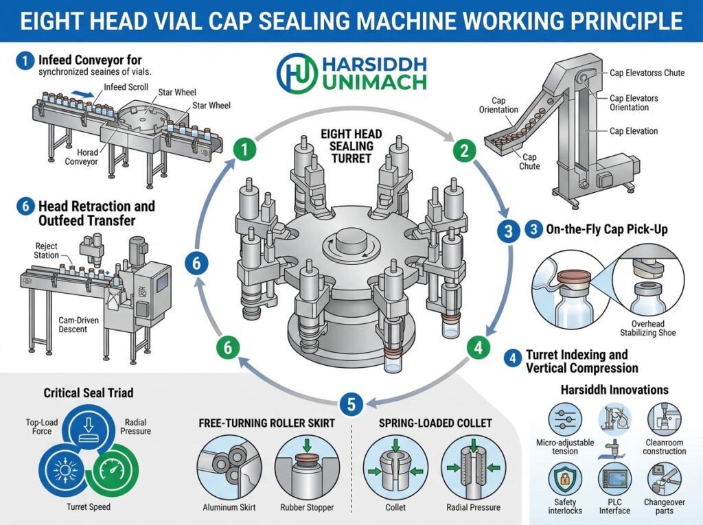
On a high-speed injectable vial line, the filling and stoppering machine can produce vials faster than smaller capping machines can seal them. When that happens, vials queue up, the filler slows down and the whole line loses output. The eight head vial cap sealing machine is designed to prevent this bottleneck. With eight sealing heads working in sequence on a continuously rotating turret, it crimps aluminium seals at the pace demanded by high-output lines — while keeping every crimp tight, smooth and consistent.
In this article, we explain the working principle of an eight head vial cap sealing machine, with a focus on what makes high-speed, eight-head operation different: how vials and seals are fed at speed, how the turret and heads are synchronised, how crimping is performed, how consistency is maintained across all eight heads and how to troubleshoot problems. For the fundamentals of crimping on a smaller machine, see our complete guide to the four head vial cap sealing machine working principle, and for the basics that apply to all models, read the vial cap sealing machine working principle.
What Is an Eight Head Vial Cap Sealing Machine?
It is an automatic rotary machine that places aluminium flip-off seals on stoppered vials and crimps them around the vial neck using eight sealing heads mounted on a rotating turret. Each head contains a spring-loaded plunger and crimping rollers. Because eight heads share the work, each one has more time to form a high-quality crimp, even at high line speeds.
See the Automatic Eight Head Vial Cap Sealing Machine and our 1, 4, 6 and 8 head vial cap sealing machines.
Why Eight Heads?
The number of heads determines how much time each crimp gets at a given line speed:
- On a machine with fewer heads, each head must complete its crimp quickly to keep up with a fast line.
- On an eight head machine, the work is divided among more heads, so each head can rotate more slowly relative to the vial flow — giving rollers more time to form the seal smoothly.
The result is high throughput without rushing the crimping process. For a full comparison of output and applications, read eight head vs single head vial cap sealing machine.
Main Assemblies
- Infeed conveyor and guides – receive stoppered vials from the filler
- Infeed worm (scroll) – separates vials and spaces them at the correct pitch
- Infeed star wheel – transfers vials into the turret
- Cap hopper and vibratory bowl – store and orient aluminium seals
- Cap chute and pick-off – deliver one seal to each passing vial
- Rotary turret with eight sealing heads – the core crimping assembly
- Plungers (pressure pads) – apply top pressure to the seal and stopper
- Crimping rollers – fold the seal skirt under the vial neck flange
- Outfeed star wheel and conveyor – discharge sealed vials
- Main drive and controls – synchronise all movements and monitor operation
Eight Head Vial Cap Sealing Machine: Assemblies and Drive
Step-by-Step Working Principle
Step 1: High-speed vial infeed
Stoppered vials arrive from a high-output filling and stoppering machine — such as the Automatic Rotary Vial Filling Machine, our liquid vial filling machine with rubber stoppering or, for powders, the double wheel injectable dry powder filling machine with vial rubber stoppering.
At high speed, simply pushing vials into a star wheel can cause jams and breakage. An infeed worm — a helical screw — separates the vials gently and delivers them at exactly the right pitch to the infeed star wheel, which transfers each vial smoothly into a turret pocket.
Step 2: Cap feeding at speed
The vibratory bowl must supply seals continuously at the line rate. Tooling in the bowl orients each seal correctly, and the chute delivers a steady stream to the pick-off point. A level sensor in the chute controls bowl vibration, keeping the supply constant without overfilling.
As each vial passes the pick-off, its stopper catches a seal from the end of the chute and carries it away, seated loosely on top. Precise alignment of the pick-off with the vial path is critical — at high speed, even small misalignments cause missing or tilted seals.
Step 3: Entry into the eight-head turret
The vial, carrying its loose seal, enters a turret pocket aligned beneath one of the eight sealing heads. The turret rotates continuously, carrying vials and heads together.
Step 4: Head descent and top pressure
A stationary cam track around the turret guides each head downward as it rotates. The head’s spring-loaded plunger contacts the seal and presses it — and the stopper beneath — firmly onto the vial lip. Spring force sets the top pressure, which must be enough to compress the stopper properly without stressing the glass.
Step 5: Roller crimping
With the seal held down, the crimping rollers move inward against the seal skirt. As the head spins relative to the vial (or the rollers orbit the neck), the rollers travel around the full circumference, progressively folding the soft aluminium under the neck flange. The aluminium is permanently formed into a tight, smooth band that locks the stopper in place.
Key factors include roller profile, roller height, roller pressure and the number of rotations completed during the crimp. Learn more about why these matter in how crimping force affects container closure integrity.
Step 6: Head lift and discharge
As the turret continues, the cam track lifts the head and the rollers retract. The sealed vial is transferred to the outfeed star wheel and onto the conveyor, while the head returns to the infeed to receive the next vial.
How Eight-Head Operation Is Synchronised
Mechanical synchronisation
A main motor drives the turret, infeed worm, star wheels and conveyor through a gearbox and timing gears, so all motions remain locked together. When the speed changes, every part changes speed proportionally.
Speed matching with the line
A variable frequency drive sets machine speed to match the filler. The capping machine is normally run slightly faster than the filler so it can recover after short upstream stoppages. Sensors on the infeed and outfeed conveyors can pause or slow the machine automatically if vials back up or run short.
Continuous motion
Because the turret rotates continuously rather than stopping and starting, vials experience smooth, steady movement — important for gentle glass handling at high speeds.
Maintaining Consistency Across Eight Heads
With eight heads, consistency becomes as important as speed. Each head must apply the same top pressure and form the same crimp. In practice, this means:
- Matched springs in all plungers, replaced as sets
- Identical roller settings for height and pressure across all heads
- Even wear monitoring — one worn roller can cause defects on every eighth vial
- Head-by-head sampling during in-process checks
- Clear identification of each head so defects can be traced quickly
A defect pattern that repeats every eighth vial is a strong indicator that one specific head needs attention.
Controls and Safety Features
- No-vial-no-cap logic to prevent seals being fed into empty positions
- Missing cap detection and automatic rejection where fitted
- Chute level sensing to control cap supply
- Infeed and outfeed jam detection
- Guard interlocks and emergency stops
- Production counters and alarm displays
Key Settings and Their Effects
| Setting | Too Low | Too High |
|---|---|---|
| Plunger (top) pressure | Loose seal, stopper not compressed | Over-compressed stopper, glass stress |
| Roller pressure | Loose skirt, seal rotates | Cracked neck, torn aluminium |
| Roller height | Crimp too high, weak grip | Roller contacts glass, chipping |
| Turret speed | Lower output | Incomplete or uneven crimps |
| Cap bowl vibration | Missing seals | Jams, damaged seals |
| Infeed pitch / worm timing | Gaps in vial flow | Crowding and breakage |
Where the Machine Fits in a High-Speed Line
- Vial washing — for example, on a linear vial washing machine
- Depyrogenation
- Filling and stoppering
- Cap sealing — the eight head machine
- External washing — on an automatic external vial washing machine
- Inspection — on a visual ampoule and vial inspection machine
- Labelling — for example, the Automatic Vial Sticker Labeling Machine
Each machine must be balanced in speed so the line runs smoothly. For broader guidance on running fast lines, read challenges in high-speed vial processing and their solutions.
Checking Crimp Quality
- Visual inspection – smooth, even crimp without wrinkles, pleats, tears or tilted seals
- Rotation or torque check – seal should not rotate when tested by the approved method
- Neck inspection – no cracks or chips
- Head-by-head sampling – samples taken from each of the eight heads
- Residual seal force testing – in some facilities, specialised instruments measure the remaining compression on the stopper
- Container closure integrity testing – during validation
Troubleshooting Guide
| Problem | Likely Cause | Corrective Action |
|---|---|---|
| Defect on every eighth vial | One head out of adjustment or worn | Inspect and adjust that head’s rollers and spring |
| Loose seals across all heads | Low roller pressure, wrong change parts | Increase pressure, verify parts |
| Wrinkled skirts | Roller height or profile mismatch, excessive speed | Adjust height, check profile, reduce speed |
| Cracked necks | Excessive pressure, misaligned head | Reduce pressure, realign |
| Missing seals | Chute empty, pick-off misaligned | Refill bowl, realign pick-off |
| Vial jams at infeed | Incorrect worm timing or guides | Adjust timing and guides |
| Raised stoppers after capping | Stopper not fully seated upstream | Check stoppering station |
Maintenance Essentials
- Daily: remove aluminium dust from heads, rollers and turret; check guards and sensors
- Regularly: inspect rollers, springs and plungers on all eight heads; replace worn parts as sets
- Periodically: check cam tracks, bearings, gearbox and drive components; lubricate as specified
- Change parts: keep star wheels, worms and guides for each vial size clean, labelled and in good condition
- Spares: stock rollers, springs and plungers for every head
Changeover Between Vial Sizes
When switching vial or seal sizes, operators change the infeed worm, star wheels, guides and cap chute, then adjust head height and roller settings for all eight heads. Trial vials are run and checked head by head before production restarts. Clearly labelled change parts and recorded settings for each format keep changeovers fast and consistent.
Choosing an Eight Head Machine
An eight head machine is ideal when:
- Your filling line runs at high speed
- You produce large volumes of vials continuously
- You need consistent crimp quality at high output
- A smaller capper is limiting line performance
For smaller outputs, four or six head machines may be more economical. Explore the full range of glass vial capping machines, all capping machines on Harsiddh Engineering and our vial filling machines for liquid vials to plan the complete line.
Frequently Asked Questions
How does an eight head vial cap sealing machine work? Vials pick up aluminium seals from a chute and enter a continuously rotating turret, where eight heads take turns pressing each seal down with a plunger and crimping it under the vial neck with rollers.
Why use eight heads instead of four? Eight heads share the crimping work, so each crimp gets enough time even at high line speeds, delivering high output with consistent quality.
What does a defect every eighth vial mean? It usually indicates one specific head with worn rollers, a weak spring or incorrect adjustment.
How is the capper matched to the filler? A variable frequency drive sets the capper speed slightly above the filler’s, with sensors to pause or slow the machine if vials back up.
What maintenance does an eight head machine need? Regular removal of aluminium dust, inspection and replacement of rollers, springs and plungers on all heads, and periodic checks of drives and cam tracks.
Need a high-speed vial cap sealing machine for your line? Explore our capping machines, contact our team or send an inquiry.