
/ Pharma Machinery / By Harsiddh Unimach
In a Current Good Manufacturing Practice (cGMP) pharmaceutical manufacturing environment, a liquid filling machine is never a standalone piece of hardware. It functions as the core node of a highly complex, interconnected ecosystem where machine performance is directly dependent on the quality, pressure, and volume of incoming plant utilities.
Whether you are executing a greenfield formulation project or upgrading an existing sterile parenteral or oral liquid line, understanding the exact utility requirements for pharmaceutical liquid filling machines is critical. Improper utility sizing, contaminated lines, or fluctuating pressure drops do not just cause mechanical downtime—they present severe risks to product sterility, dose accuracy, and regulatory compliance.
As a premier manufacturer of high-performance pharmaceutical packaging machinery, Harsiddh Unimach Pvt. Ltd. designs advanced liquid filling systems that seamlessly interface with standard cleanroom utilities. This comprehensive engineering guide breaks down the critical electrical, pneumatic, clean utility, and environmental infrastructure required to commission and operate an industrial-grade pharmaceutical liquid filling line.
1. Electrical Power Supply Requirements & Quality Stability
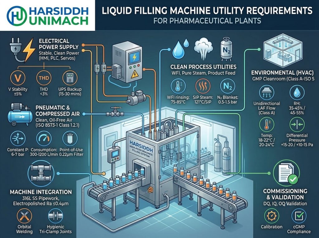
Pharmaceutical liquid filling machines utilize multi-axis servo motors, variable frequency drives (VFDs), programmable logic controllers (PLCs), and human-machine interfaces (HMIs) to achieve precise filling tolerances. These micro-electronics demand an exceptionally stable and clean electrical architecture.
Voltage, Phase, and Frequency Standards
Depending on your global manufacturing facility’s location, filling lines from Harsiddh Unimach Pvt. Ltd. are engineered to match standard industrial grids:
- Three-Phase Power: Typically 380V / 415V / 480V AC (±5%), 50Hz or 60Hz plus Neutral and dedicated Clean Earth (Ground).
- Single-Phase Control Power: Internal step-down transformers convert power to 230V AC or 24V DC for control sensors, safety light curtains, and PLC modules.
Harmonic Distortion and Voltage Fluctuations
Transient voltage surges, sags, and high-frequency harmonics generated by heavy plant equipment (like large chillers or HVAC compressors) can corrupt PLC data packets, leading to intermittent tracking errors or unexpected machine stops.
- Voltage Stability: The incoming line voltage must be stabilized within ±5% of the nominal value. If the plant grid experiences larger fluctuations, installing a dedicated Industrial Voltage Stabilizer or Servo Control Transformer is mandatory.
- Total Harmonic Distortion (THD): Voltage THD must be restricted to less than 3% to protect delicate servo drives from overheating and premature failure.
- UPS Backup: A centralized or machine-integrated Uninterruptible Power Supply (UPS) with a minimum 15-to-30 minute backup time is highly recommended. This ensures that in the event of a sudden power outage, the filling nozzles can complete their active cycle, retract cleanly, and the PLC can execute a structured, data-safe shutdown without damaging mechanical components or wasting sterile product.
2. Pneumatic & Compressed Air Specifications
Pneumatic energy drives critical sub-assemblies inside a liquid filler, including container indexing gates, diving nozzle lift cylinders, liquid shut-off valves, and sorting bowls. Because this air operates within or directly adjacent to the sterile filling zone, its purity must be strictly regulated.
[Plant Air Compressor] ➔ [Refrigerated Dryer] ➔ [Coalescing Filters (0.01µm)] ➔ [Machine Point of Use (0.22µm Sterile Filter)]
Pressure and Flow Rate Baselines
- Constant Operating Pressure: A minimum of 6 bar to 7 bar (87 to 101 PSI) must be maintained continuously at the machine’s inlet manifold.
- Consumption Volumetric Flow Rate: Depending on the number of heads (e.g., a 4-head linear vs. a 24-station high-speed rotary filler), the pneumatic consumption ranges from 300 Liters/Minute to over 1200 Liters/Minute.
ISO 8573-1 Air Quality Classifications
Standard industrial “shop air” is absolutely prohibited in pharmaceutical packaging environments. Incoming compressed air must meet ISO 8573-1 Class 1.2.1 parameters:
- Solid Particles (Class 1): Particle sizes in the surrounding filling environment must be minimized. Point-of-use filtration must include a 0.22 µm sterile-grade hydrophobic filter to catch micro-particulates.
- Humidity / Dew Point (Class 2): The pressure dew point must be ≤ −40°C (−40°F). This ensures that no moisture drops condense inside the internal pneumatic lines or valves, preventing internal bacterial proliferation and corrosion.
- Total Oil Content (Class 1): Oil vapor concentration must not exceed 0.01 mg/m³. The plant must utilize strictly oil-free screw compressors. Hydrocarbon vapor carryover can alter product chemistry or ruin container surface sterility.
3. Clean Process Utilities: WFI, Pure Steam, and Product Feed
For injectable formulations, ophthalmic solutions, and high-purity oral syrups, the utilities that interact directly with product contact surfaces must undergo rigorous validation.
Water for Injection (WFI) & Purified Water (PW)
Liquid filling pumps, syringes, and fluid paths require routine cleaning. WFI is utilized for final rinsing during Clean-in-Place (CIP) routines to eliminate chemical residues and pyrogens.
- WFI Line Temperature: Maintained continuously at 75°C to 85°C within the looping supply line to prevent biofilm development.
- Conductivity Limits: ≤1.3 µS/cm at 25°C in strict compliance with USP/EP standards.
Clean/Pure Steam for SIP (Sterilize-in-Place)
If your Harsiddh Unimach Pvt. Ltd. filling machine is configured for aseptic processing, the product contact manifold will utilize a Sterilize-in-Place system to sterilize the lines without manual disassembly.
- Pure Steam Quality: Derived from a dedicated pure steam generator using feed water devoid of volatile water treatment chemicals. The steam must be dry, saturated, and non-condensable gas free.
- Operating Temperature & Pressure: The system must supply pure steam at 2.0 to 2.5 bar, achieving a sustained sterilization core temperature of 121°C (250°F) for a validated duration (typically 30 minutes) across all product contact paths.
Product Feeding Hydraulics & Head Pressure
To achieve precise volumetric displacement (whether via piston pumps, peristaltic modules, or mass flow meters), the product supply line must deliver fluid under uniform pressure:
- Gravity Feed / Pressure Vessels: If using a pressurized product tank, a steady blanket of ultra-pure Nitrogen (N₂) gas is maintained at 0.5–1.5 bar to drive viscous liquids down into the dosing manifold without cavitation.
- Pumped Feed: If using a sanitary positive displacement lobe pump, VFD controls must link directly to the filler’s internal buffer tank level sensors to eliminate fluid velocity surges.
4. HVAC, Cleanroom Zoning, and Exhaust Infrastructure
The environment enclosing the filling machine dictates the safety profile of the finished batch. The machine’s physical frame layout must balance seamlessly with the facility’s heating, ventilation, and air conditioning (HVAC) infrastructure.
| Cleanroom Parameter | Aseptic / Sterile Filling (Class A / Grade A / ISO 5) | Non-Sterile Oral Liquids (Class C/D / Grade C/D) |
|---|---|---|
| Airflow Pattern | Unidirectional Laminar Airflow (LAF) | Turbulent / Mixed Airflow |
| Air Velocity | 0.45 m/s ±20% (90 FPM) | Not strictly controlled by velocity |
| Relative Humidity | 35%–45% RH | 45%–55% RH |
| Differential Pressure | +15 to +20 Pascals vs. adjacent rooms | +10–+15 Pascals vs. corridors |
| Room Temperature | 18–22°C (64–72°F) | 20–24°C (68–75°F) |
Localized Extractors for Off-Gassing or Dust
Certain pharmaceutical formulations exhibit volatile characteristics or emit heavy vapors during open-container filling phases. In these cases, the machine zone must integrate a local spot-exhaust manifold hooked into the plant’s safe-vent extraction line to prevent chemical inhalation by machinery operators.
5. Machine Integration, Pipework, and Structural Materiality
Connecting utilities to a premium liquid filler requires specific structural materials to preserve cleanroom validations:
- Piping Metallurgy: All process utility connection pipes (WFI, Pure Steam, Product Feed) must consist entirely of 316L Stainless Steel, internally electropolished to a surface roughness (Ra) of ≤0.4 µm to inhibit bacterial adhesion.
- Orbital Welding Requirement: All permanent pipe joints linking the facility utilities to the machine manifold must utilize automated orbital welding. Manual stick or TIG welding creates carbon precipitation pits that compromise sterility.
- Tri-Clamp Sanitary Fittings: Removable links must utilize hygienic tri-clamp connections backed by FDA-approved, medical-grade gaskets (such as EPDM, PTFE, or Silicone) that resist regular sterilization scaling.
- Floor Drainage Layout: High-capacity filling rooms require specialized stainless steel box-drains equipped with vapor traps located near the machine perimeter to handle high-volume CIP fluid dump discharges efficiently.
6. Pre-Commissioning Validation Framework (DQ, IQ, OQ)
Before a liquid filling line from Harsiddh Unimach Pvt. Ltd. can run commercial pharmaceutical batches, the utility connections undergo careful scrutiny during the formal validation cycle.
[Design Qualification - DQ] ➔ [Installation Qualification - IQ] ➔ [Operational Qualification - OQ]
Design Qualification (DQ)
Verifies that the plant utility capacities match or exceed the worst-case consumption rates of the machinery. Engineers check that the transformer kVA, compressor CFM, and WFI loop heating capacities can sustain peak machinery output speeds.
Installation Qualification (IQ)
Physical verification of the machine footprint. This stage documents that:
- Incoming pipe materials match 316L SS specifications via material test reports (MTR).
- Instruments like pressure gauges, flow sensors, and temperature RTDs are certified and calibrated against NIST-traceable standards.
- Electrical wiring conforms to local safety codes and contains adequate circuit shielding.
Operational Qualification (OQ)
Tests the utility thresholds during active operation. The machine is challenged under boundary conditions—such as intentionally lowering air pressure to 5.5 bar—to ensure that the low-pressure alarms trigger instantly, halt production safely, and prevent sub-standard vials or bottles from advancing through the line.
Why Partner with Harsiddh Unimach Pvt. Ltd.?
Engineering a synchronized liquid packaging line requires deep mechanical alignment and a complete understanding of international pharmaceutical regulations. At Harsiddh Unimach Pvt. Ltd., we design and manufacture high-efficiency machinery that conforms strictly to global regulatory baselines, including US FDA, EU GMP, and WHO standards.
Our Engineering and Integration Advantages:
- Utility-Optimized Form Factors: Our machines utilize premium low-consumption pneumatic and high-efficiency servo drives, directly lowering your plant’s overall operational energy footprint.
- Flawless Automation Integration: Every system features a validated PLC architecture configured for secure batch reporting, comprehensive alarms, and complete compliance with 21 CFR Part 11 electronic record protocols.
- Full Validation Support Documentation: We back our machinery deliveries with exhaustive DQ, IQ, and OQ protocol documentation packages to accelerate your facility’s regulatory approval cycles.
- Turnkey Cleanroom Solutions: From standalone compact vial fillers to high-throughput, fully enclosed linear or rotary bottle filling, capping, and tracking lines—our systems are custom-tailored to minimize structural footprint and maximize OEE.
Streamline Your Plant Validation and Scale Up Output
Don’t let inadequate utility planning delay your next pharmaceutical production launch. Optimize your manufacturing floor by deploying precision-engineered machinery backed by professional system integration support.
For detailed technical specification catalogs, utility consumption matrix tables, or customized project engineering quotes, contact our technical consulting team directly:
- Corporate Web Platform: www.harsiddhunimach.com
- Technical Inquiry Hub: info@harsiddhunimach.com
- Global Headquarters: Harsiddh Unimach Pvt. Ltd., Gujarat, India.