
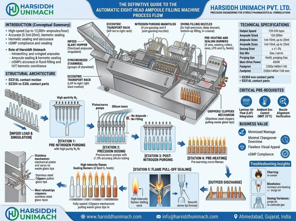
An automatic eight head ampoule filling and sealing machine is one of the most productive machines in an injectable plant. Every machine cycle, it moves eight ampoules forward together, purges them with nitrogen, fills them with an accurate dose, protects the headspace, heats their necks and pull-seals them — while the next groups of ampoules are already being processed behind them.
Understanding this process flow in detail helps operators set up and run the machine correctly, helps engineers diagnose problems quickly and helps quality teams understand where each critical parameter is controlled. In this definitive guide, we follow ampoules through every station of a typical eight head machine, explain what makes eight-position operation different from smaller machines, and cover setup, in-process checks, changeover and troubleshooting.
If you are deciding whether an eight head machine is right for your plant, start with our article on why choose an automatic eight head ampoule filling and sealing machine. For the general principles behind all ampoule machines, see our ultimate guide to the ampoule filling and sealing machine working principle.
Where the Machine Sits in the Line
In high-volume production, an eight head machine is almost always part of an integrated line:
- Ampoule washing – a washer such as the Automatic Rotary Ampoule Washing Machine cleans ampoules inside and out. See our full range of ampoule washing machines.
- Sterilisation and depyrogenation – a sterilizing tunnel for ampoules and vials dries, sterilises and cools the ampoules.
- Filling and sealing – the eight head machine.
- Inspection and labelling – downstream quality checks and identification.
The tunnel discharges sterile ampoules directly into the eight head machine’s infeed, so ampoules move from washing to sealing with minimal manual handling.
Process Flow at a Glance
- Infeed from the tunnel
- Separation and transport into eight-ampoule groups
- Pre-gassing (eight positions)
- Filling (eight needles, eight pumps)
- Post-gassing (eight positions)
- Pre-heating (eight positions)
- Sealing with pull-sealing tongs (eight positions)
- Discharge and cooling
- Transfer to inspection
Eight Head Ampoule Machine: Nine Stations, Eight Ampoules at a Time
Station 1: Infeed
Sterile ampoules leave the tunnel’s cooling zone onto the infeed of the filling machine — usually an inclined infeed table or hopper under unidirectional airflow. Ampoules roll forward by gravity, guided by side rails, towards the transport system.
Key points:
- Infeed must be continuous so all eight positions are filled every cycle
- Ampoules must be cool enough not to affect the product or sealing
- Gentle movement prevents glass-to-glass impacts and breakage
Station 2: Separation and Transport
The transport system — commonly a walking beam or rack-and-pinion mechanism with serrated (V-groove) plates — picks up ampoules from the infeed and advances them in steps. With each cycle, the moving plates lift every ampoule on the machine, move it forward by one group position and set it down on the fixed plates.
On an eight head machine, the transport is arranged so that eight ampoules arrive together at each processing station. Precise groove pitch and plate alignment are essential, because any misalignment is repeated across eight positions.
Key points:
- Change parts must match ampoule diameter exactly
- Smooth acceleration and deceleration reduce tilting and breakage
- Sensors confirm that ampoules are present in each position
Station 3: Pre-Gassing
Eight gassing needles descend into the eight ampoules and flush them with filtered nitrogen, displacing air before filling.
Eight-head specifics: nitrogen is distributed through a manifold to eight needles. Flow must be balanced so that every position receives the same gas flow — an imbalance means some ampoules may retain more oxygen than others.
Station 4: Filling
Eight filling needles, mounted on a common carriage, dive into the eight ampoules. Each needle is connected to its own dosing pump. As the pumps deliver the dose, the carriage rises so the needle tips stay just above the rising liquid level, preventing foaming and keeping the necks dry. A short suck-back at the end of each dose draws the last drop back into the needle.
Dosing systems
- Syringe-type piston pumps – the traditional design, with stroke adjusted mechanically or by servo
- Servo-driven pumps – fill volume, speed and suck-back set from the HMI, with individual fine-tuning per head. See the principle in our servo based piston filling machine.
For a comparison of how product can be drawn and delivered, read vacuum filling vs gravity filling in ampoule machines.
Eight-head specifics: each of the eight pumps must be calibrated so all heads deliver the same dose. Fill weight checks should sample every head, and any head that drifts should be adjusted individually.
Station 5: Post-Gassing
A second set of eight gassing needles flushes the headspace above the liquid with nitrogen, protecting the product until the neck is sealed. Flow is timed to avoid splashing liquid onto the necks.
Station 6: Pre-Heating
The ampoules move into the sealing zone. Rollers begin rotating each ampoule while pre-heating burners warm the necks gently.
Why it matters: gradual heating reduces thermal stress and prepares the glass for a uniform seal.
Eight-head specifics: eight burner positions must produce matching flames. Gas and oxygen are supplied through manifolds, and each burner must be aligned so it heats the same point on each neck.
Station 7: Sealing
Main sealing burners heat the rotating necks to their softening point. Pull-sealing tongs then grip the tips of all eight ampoules and pull them away, separating the excess glass and forming smooth, rounded seals. The cut tips are discarded into a collection tray.
Critical parameters:
- Gas-oxygen ratio and pressure — for a stable, clean flame
- Burner alignment — focused on the neck constriction
- Rotation speed — for uniform heating
- Tong timing and grip — for consistent tip length and shape
Eight-head specifics: seal consistency must be checked across all eight positions. A difference in one burner or tong shows up as a pattern of defects on every eighth ampoule — a useful clue during troubleshooting.
Station 8: Discharge and Cooling
Sealed ampoules are transferred onto the outfeed tray or conveyor, where they cool gradually.
Station 9: Transfer to Inspection and Labelling
Ampoules move to leak testing and visual inspection — for example, on a visual ampoule and vial inspection machine — then to labelling on equipment such as the Automatic Rotary Ampoule Sticker Labeling Machine or our horizontal ampoule sticker labelling machine. Follow our best practices for ampoule and vial inspection to get consistent results.
Station Summary Table
| Station | Action | Key Control |
|---|---|---|
| Infeed | Receive sterile ampoules from tunnel | Continuous, gentle flow |
| Transport | Advance ampoules in groups of eight | Plate alignment, change parts |
| Pre-gassing | Displace air with nitrogen | Balanced flow across 8 needles |
| Filling | Dose product with diving needles | Calibration of 8 pumps |
| Post-gassing | Protect headspace | Flow timing, no splashing |
| Pre-heating | Warm necks while rotating | Matched flames |
| Sealing | Melt and pull-seal necks | Gas ratio, alignment, tong timing |
| Discharge | Transfer sealed ampoules | Gradual cooling |
How the Machine Cycle Is Synchronised
All stations operate simultaneously on different groups of ampoules. In one cycle, while one group is being filled, the group ahead is being post-gassed or sealed and the group behind is being pre-gassed. The main drive — mechanical camshaft or coordinated servo axes — ensures that transport, needle carriages, pumps, gassing valves and tongs act in exactly the right order. Speed is set to match tunnel output and downstream capacity.
Safety and quality interlocks include no-ampoule-no-fill sensing, flame failure detection, gas pressure monitoring, guard door switches and emergency stops.
Setting Up the Machine
A typical setup sequence before production:
- Verify line clearance and machine cleanliness.
- Fit change parts for the ampoule size: transport plates, guides, needles and tongs.
- Install sterilised product-contact parts — pumps, tubing and needles.
- Prime the product path to remove air.
- Set fill volume and calibrate all eight heads using weighed samples.
- Set nitrogen flow for pre- and post-gassing and check balance across positions.
- Light and adjust burners — gas-oxygen ratio, flame size and alignment for all eight positions.
- Adjust rotation and tong timing for the ampoule size.
- Run trial ampoules and inspect fill volume, seal shape and tip quality at every position.
- Record settings and obtain approval to start production.
In-Process Checks
- Fill weight checks for each of the eight heads at defined intervals
- Seal inspection — tip shape, length and absence of capillaries or charring at every position
- Nitrogen flow verification
- Flame appearance across all burners
- Breakage monitoring and cause investigation
- Reject trends by position to detect drift early
Changeover Between Ampoule Sizes
- Complete the batch and clear the machine.
- Remove and clean product-contact parts.
- Change transport plates, guides, needles and tong components.
- Adjust burner positions and heights.
- Select or set parameters for the new size.
- Calibrate all eight heads and run trial ampoules.
- Complete documentation and line clearance.
Open vs Closed Ampoule Process Flow
For closed ampoules, an extra tip-opening station is added before pre-gassing: the sealed tips are heated and cut or broken, and glass fragments are removed by suction. The rest of the flow is the same. See our eight head closed ampoule filling and sealing machine and the full range of ampoule filling machines for closed ampoules.
Troubleshooting by Station
| Symptom | Likely Station | Typical Cause |
|---|---|---|
| Fill variation on one head | Filling | Pump wear, air in line, calibration |
| Charred tips | Filling / post-gassing | Wet necks from splashing or drips |
| Defect repeating every eighth ampoule | Sealing / filling | One burner, tong or pump out of adjustment |
| Leaking seals or capillaries | Sealing | Gas ratio, burner alignment, tong timing |
| Bulged or long tips | Sealing | Overheating, late pull |
| Broken ampoules | Infeed / transport | Misaligned plates, wrong change parts |
| High residual oxygen | Gassing | Unbalanced or low nitrogen flow |
Understanding the process flow — and mapping each defect to its station and position — turns troubleshooting from guesswork into a quick, logical process. For a labelled visual of machine parts, see our guide to understanding the ampoule filling machine diagram and working process.
Preventive Maintenance for Consistent Process Flow
With eight positions running every cycle, wear adds up quickly. A preventive plan should include:
- Checking pump seals, valves and needles on all eight heads
- Cleaning burner nozzles and verifying flame uniformity
- Inspecting tongs, rollers and transport plates for wear
- Checking gas manifolds, regulators and hoses for leaks
- Keeping critical spares for every position in stock
Machines to Explore
- Automatic Eight Head Ampoule Filling & Sealing Machine
- Eight head ampoule filling and sealing machine on Harsiddh Engineering
- High-speed eight head vertical ampoule filling and sealing machine
Frequently Asked Questions
What is the process flow of an eight head ampoule filling machine? Ampoules move from the tunnel infeed into groups of eight, then pass through pre-gassing, filling, post-gassing, pre-heating and pull sealing before being discharged for inspection.
Why must all eight heads be calibrated individually? Each head has its own pump and needle, so small differences can cause fill variation. Individual calibration ensures every ampoule receives the same dose.
What does a defect on every eighth ampoule indicate? It usually points to one specific position — a pump, burner or tong — that needs adjustment.
How is nitrogen distributed to eight positions? Through a manifold feeding eight gassing needles, with flow balanced so each ampoule receives the same protection.
How does the process differ for closed ampoules? A tip-opening station is added before gassing and filling; the rest of the process flow is the same.
Want to see an eight head ampoule filling machine in action? Explore our ampoule filling machine range, contact our team or send an inquiry.