
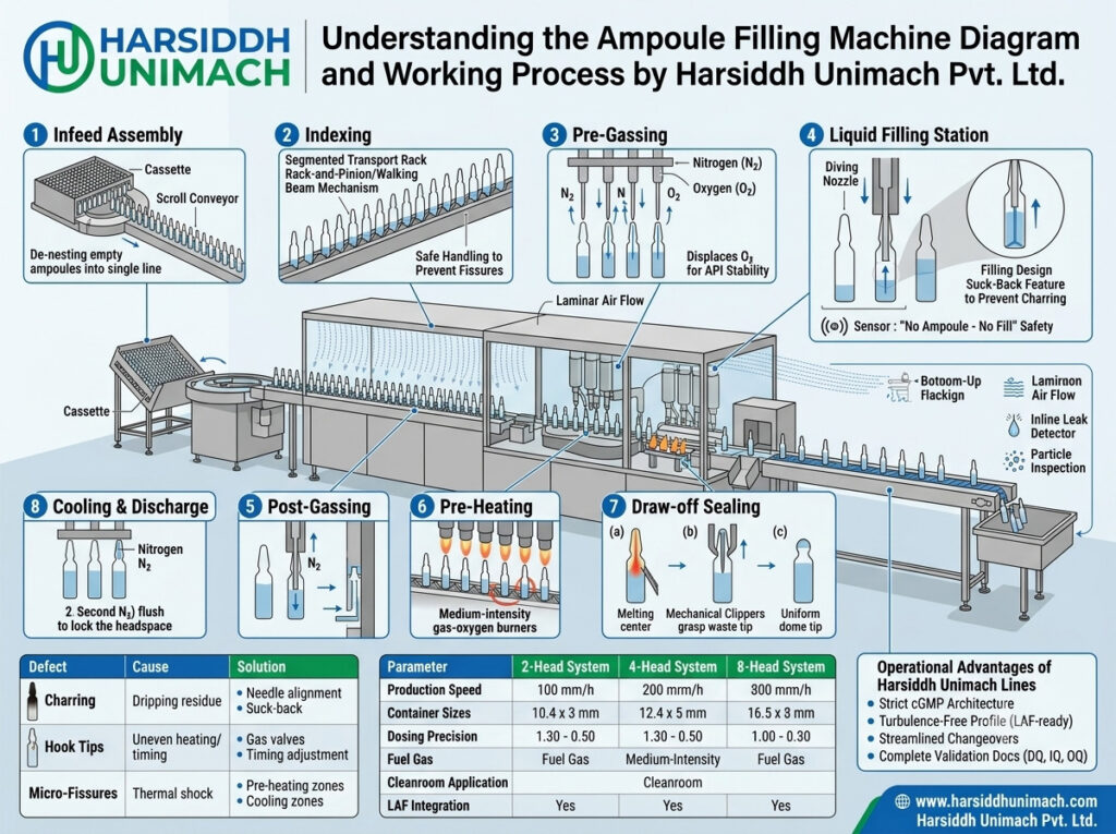
A diagram is often the fastest way to understand a machine. When operators, engineers, quality staff or buyers look at an ampoule filling machine for the first time, the cluster of needles, pumps, burners, gas lines and moving plates can seem complicated. Once each part is identified and its role in the process is clear, the whole machine makes sense.
In this guide, we walk through a labelled diagram of an ampoule filling and sealing machine, explaining every numbered part and how it contributes to the working process. We then follow an ampoule through the machine from infeed to outfeed. For a deeper look at the engineering behind each mechanism, read our companion article: the ultimate guide to ampoule filling and sealing machine working principle.
How to Read the Diagram
The diagram shows a simplified side view of a typical automatic ampoule filling and sealing machine. Ampoules enter on the left, move to the right through each processing zone and leave on the right. The machine can be divided into four horizontal layers:
- Bottom layer: the machine base and main drive (14), which power and synchronise every movement.
- Ampoule level: the transport system (2), where ampoules sit in grooves and move step by step.
- Processing level: gassing needles (3, 7), filling needles (4), burners (8, 9) and pull-sealing tongs (10), which act on the ampoules.
- Supply and control level: the product tank (6), dosing pumps (5), gas control panel (12) and control panel (13).
Let’s look at each numbered part in turn.
Part-by-Part Explanation
1. Infeed hopper
The infeed hopper receives sterilised, depyrogenated ampoules. On standalone machines, operators load ampoules from trays; on integrated lines, ampoules arrive directly from the sterilising tunnel. The hopper is inclined so ampoules roll gently forward under gravity into the transport system, with side guides keeping them in order.
Why it matters: smooth, controlled infeed prevents ampoules from jamming, tilting or striking each other — a major cause of breakage and glass particles.
2. Transport system (walking beam)
The transport system moves ampoules from station to station. Ampoules rest in V-shaped grooves on serrated plates. A moving set of plates lifts all ampoules, advances them by one position and sets them down, while fixed plates hold them in place between movements. This intermittent motion ensures that ampoules are perfectly still while they are gassed, filled and sealed.
Why it matters: groove pitch must match the ampoule diameter, which is why change parts are needed for each size. Our article on reducing downtime during ampoule size changeovers explains how to change these parts efficiently.
3. Pre-gassing needle
Before filling, a gassing needle enters each ampoule and flushes it with nitrogen to displace air and oxygen.
Why it matters: oxygen-sensitive products can degrade or discolour if exposed to oxygen. Pre-gassing protects stability from the very first drop of liquid.
4. Filling needles
Stainless steel filling needles, mounted on a moving carriage, enter the ampoule necks and dispense the liquid. In well-designed machines, the needles go deep into the ampoule and rise as the liquid level increases.
Why it matters: bottom-up filling prevents foaming and keeps the neck dry. A wet neck chars during sealing, causing black tips, weak seals and rejects.
5. Dosing pumps
Each filling needle is connected to its own dosing pump. Pumps may be syringe-type (piston), servo-driven or peristaltic. The pump draws a precise volume from the supply line and pushes it through the needle, often ending with a small suck-back to prevent drips.
Why it matters: pump accuracy determines fill volume consistency. Servo-driven pumps, such as those on the Automatic Servo Based Ampoule Filling and Sealing Machine, allow fill volume to be set from the HMI.
6. Product supply tank
The product supply tank or buffer vessel holds filtered, sterile liquid ready for dosing. It connects to the pumps through sterile tubing and is often fed from a larger holding vessel.
Why it matters: a stable supply with no air bubbles is essential for accurate, consistent dosing.
7. Post-gassing needle
After filling, a second gassing needle flushes the headspace above the liquid with nitrogen, keeping oxygen out until the ampoule is sealed.
Why it matters: post-gassing minimises residual oxygen inside the sealed ampoule, protecting shelf life.
8. Pre-heating burners
As ampoules enter the sealing zone, pre-heating burners gently warm the neck while rollers rotate each ampoule.
Why it matters: gradual heating reduces thermal shock and prepares the glass for a uniform seal.
9. Sealing burners
The main sealing burners use a mixture of fuel gas and oxygen to heat the ampoule neck to its softening point. The ampoule continues to rotate so the neck is heated evenly all round.
Why it matters: flame quality — controlled by the gas-oxygen ratio — determines seal strength and appearance. A stable blue flame produces clean seals; an incorrect mixture produces soot, bulbs or weak spots.
10. Pull-sealing tongs
When the neck is soft, mechanical tongs grip the tip of the ampoule and pull it away. The soft glass separates, and the flame closes the remaining neck into a smooth, rounded tip.
Why it matters: pull sealing produces stronger, more uniform seals than simple tip sealing and is preferred for pharmaceutical injectables.
11. Outfeed tray
Sealed ampoules are transferred onto an outfeed tray, where they cool before moving on to leak testing, inspection and labelling.
Why it matters: gradual cooling avoids stress cracks, and an orderly outfeed simplifies handling.
12. Gas control panel
The gas control panel houses regulators, flow meters and valves for fuel gas, oxygen and nitrogen. It controls flame intensity and gassing flow.
Why it matters: stable gas pressures and flows are essential for consistent seals and effective nitrogen protection. Flame failure and pressure monitoring improve safety.
13. Control panel (PLC and HMI)
The control panel contains the PLC and the HMI touchscreen used to start and stop the machine, set speeds, adjust parameters, view alarms and count production.
Why it matters: recipe management and clear alarms make operation easier and settings more repeatable.
14. Main drive and servo system
The main drive powers the transport, needle carriage, pumps and tongs. In traditional machines, a single motor drives a camshaft that synchronises all movements mechanically. In modern machines, servo motors drive key functions under electronic control.
Why it matters: precise synchronisation ensures that needles, flames and tongs act at exactly the right moment for each ampoule.
Materials and GMP Design Behind the Diagram
A diagram shows where parts are, but not what they are made of — and in pharmaceutical machines, materials matter as much as layout:
- Product-contact parts such as filling needles, pump components and tubing connections are typically made of SS 316L or approved pharmaceutical-grade materials, with smooth, polished surfaces.
- Machine frame and covers are usually SS 304, designed without sharp corners or ledges where dust can collect.
- Transport plates and change parts must be precisely machined so ampoules sit correctly without scratching.
- Burner components are made from heat-resistant materials and must be easy to remove for cleaning.
- Guarding made of transparent panels allows operators to see the process while protecting them from moving parts and flames.
These choices make the machine easier to clean, validate and maintain under GMP.
Following an Ampoule Through the Machine
Now that each part is identified, here is the journey of a single ampoule:
- Infeed (1): the sterile ampoule rolls from the hopper into the transport grooves.
- Transport (2): it moves forward one position at a time.
- Pre-gassing (3): nitrogen displaces air inside the ampoule.
- Filling (4, 5, 6): the needle dives in, the pump doses the liquid from the supply tank, and the needle rises and withdraws without dripping.
- Post-gassing (7): nitrogen protects the headspace.
- Pre-heating (8): the neck is gently warmed as the ampoule rotates.
- Sealing (9, 10): the neck softens in the flame and the tongs pull the tip away to seal it.
- Outfeed (11): the sealed ampoule cools on the outfeed tray.
Throughout the journey, the gas panel (12), control panel (13) and main drive (14) keep every step synchronised and controlled.
How the Diagram Changes for Different Machines
The basic diagram applies to most ampoule filling and sealing machines, but some details vary.
Number of heads
The number of filling needles, pumps and sealing positions increases with machine size:
- Automatic Single Head Ampoule Filling & Sealing Machine – one of each, for laboratories and small batches.
- Automatic Two Head Ampoule Filling & Sealing Machine – two needles and pumps, as shown in the diagram.
- Four head ampoule filling and sealing machine – for medium production.
- Eight head ampoule filling and sealing machine – for high-volume production.
Small-scale machines follow the same principle in a compact layout; see our article on the working principle of a small-scale ampoule filling and sealing machine.
Open vs closed ampoules
The diagram shows open (funnel-type) ampoules. Machines for closed ampoules add a tip-opening station before pre-gassing, where the sealed tip is heated, cut and removed, and glass fragments are extracted by suction. See our eight head closed ampoule filling and sealing machine and compare with our ampoule filling machines for open ampoules.
Where the Machine Sits in the Complete Line
An ampoule filling and sealing machine is one part of a larger injectable line:
- Washing – ampoules are cleaned with water and air, for example on a semi-automatic multijet ampoule washing machine or an automatic rotary washer.
- Sterilisation – a sterilizing tunnel for ampoules and vials dries, sterilises and depyrogenates the ampoules.
- Filling and sealing – the machine shown in the diagram.
- Inspection – sealed ampoules are checked for particles, cracks and seal defects using a visual ampoule and vial inspection machine.
- Labelling – ampoules are labelled on dedicated labeling machines for ampoules.
Explore complete solutions in our injectable ampoule filling line category.
Using the Diagram for Troubleshooting
A clear understanding of the diagram helps teams find the source of problems quickly:
| Problem | Parts to Check |
|---|---|
| Inaccurate fill volume | Dosing pumps (5), product supply (6), filling needles (4) |
| Charred or black tips | Filling needles (4), pump suck-back (5), post-gassing flow (7) |
| Leaking or weak seals | Sealing burners (9), pull-sealing tongs (10), gas panel (12) |
| Uneven or bulbous seals | Pre-heating burners (8), rotation rollers, gas ratio (12) |
| Broken ampoules | Infeed hopper (1), transport grooves (2), tongs (10) |
| High residual oxygen | Pre- and post-gassing needles (3, 7), nitrogen flow (12) |
| Machine stops or alarms | Control panel (13), main drive (14), sensors |
For more ways to improve results, read our tips on how to optimize your ampoule filling, and for a beginner-level overview, see what is an ampoule filling machine and how does it work.
Frequently Asked Questions
What are the main parts of an ampoule filling machine? The main parts are the infeed hopper, transport system, gassing needles, filling needles, dosing pumps, product supply tank, pre-heating and sealing burners, pull-sealing tongs, outfeed tray, gas control panel, control panel and main drive.
What does the walking beam do? It lifts and advances ampoules one position at a time through the machine, holding them still while they are gassed, filled and sealed.
Why are there two gassing needles? One flushes the ampoule before filling to remove air, and the other flushes the headspace after filling to keep oxygen out until sealing.
What is the difference between pre-heating and sealing burners? Pre-heating burners gently warm the neck to reduce thermal shock, while sealing burners heat it to its softening point so it can be sealed.
How does the diagram differ for closed ampoules? Closed ampoule machines include an additional tip-opening station before gassing and filling.
Want to see an ampoule filling and sealing machine in action? Contact our team, learn more about Harsiddh Engineering or send an inquiry to discuss your requirements.