
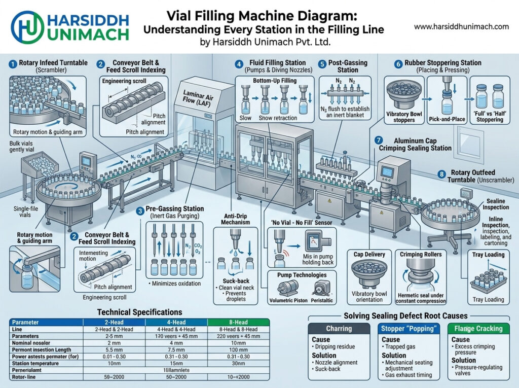
A vial filling line is not a single machine but a carefully coordinated chain of stations. Each one performs a specific task — cleaning, sterilising, filling, closing, sealing, checking or labelling — and passes the vial to the next without delay. When every station works in harmony, the line produces safe, accurately filled, sterile injectables at a steady pace. When one station falls out of step, the whole line feels it.
A clear diagram is the best way to understand how the line fits together. In this guide, we walk through a labelled vial filling line diagram station by station, explaining what each part does, why it matters and what to watch for. If you prefer a process-focused overview first, see our article on the vial filling machine working principle and process flow in pharmaceuticals.
How to Read the Diagram
The diagram shows a typical line for liquid injectables in glass vials, viewed from above:
- The top row (1–11) follows vials from infeed through washing, sterilisation, filling, stoppering, capping and external washing.
- The supply boxes (6, 8, 10) above the line feed product, stoppers and caps into the stations below.
- The green shaded area represents the Grade A zone, protected by unidirectional airflow or a RABS, where vials are open and the product is exposed.
- The bottom row (12–14) shows the downstream stations — inspection, labelling and packing.
- Line control (15) coordinates the entire line.
Station-by-Station Explanation
Station 1: Vial infeed turntable
Empty vials are loaded onto a rotating turntable, which gently guides them into a single file and feeds them to the washer at a controlled rate.
What to watch: overcrowding or jamming on the turntable causes glass-to-glass contact, chipping and breakage. Speed and guide settings should match the vial size.
Station 2: Vial washing machine
The washer cleans vials inside and out using alternating jets of recirculated water, purified water or WFI, and filtered compressed air. Vials are inverted so needles can enter and flush the interior, and water drains away freely. Many linear washers include an ultrasonic bath to loosen stubborn particles. Examples include the Automatic Linear Tunnel Type Vial Washing Machine and our linear vial washing machine.
What to watch: water and air pressures, needle condition, filter status and final rinse quality all affect cleanliness.
Station 3: Sterilising and depyrogenation tunnel
Washed vials pass directly into a hot-air tunnel with three zones:
- Infeed zone: vials enter under filtered airflow, protected from the washing room.
- Hot zone: high temperatures dry, sterilise and depyrogenate the vials, destroying microorganisms and endotoxins.
- Cooling zone: filtered air cools vials to a safe temperature before they reach the filling area.
The tunnel exit opens into the Grade A zone. See our sterilizing tunnel for ampoules and vials.
What to watch: temperature profiles, belt speed and pressure differentials must stay within validated limits. Vials must be cool enough not to damage the product.
Station 4: Infeed turntable (filling machine)
Sterile vials leaving the tunnel accumulate on an infeed turntable in the Grade A zone, which buffers the flow and feeds them into the filling machine’s transport system — usually a star wheel or infeed worm.
What to watch: the turntable must keep vials moving smoothly without tipping or crowding.
Station 5: Filling station
This is the heart of the line. Vials stop or move continuously beneath filling nozzles, which dive into the vial and dispense an accurate dose as they rise. Nitrogen purging may be added before and after filling for oxygen-sensitive products. Sensors ensure that a nozzle only fills when a vial is present.
Filling machines may be linear (intermittent) or rotary (continuous motion). For example, the Automatic Rotary Vial Filling Machine fills vials on a rotating star wheel, while our liquid vial filling machine with rubber stoppering combines filling and stoppering on one platform.
What to watch: fill accuracy, nozzle alignment, drip prevention and foaming.
Station 6: Dosing system
Above the filling station, the dosing system draws product from a sterile vessel and delivers it to the nozzles. Pumps may be piston, servo-driven or peristaltic. The product path — vessel, tubing, pumps and nozzles — is sterilised before each batch.
What to watch: air bubbles in the product line, pump calibration and tubing integrity.
Station 7: Stoppering station
Immediately after filling, rubber stoppers are placed on the vials. A pick-and-place head or a rotating stoppering wheel picks each stopper from the chute and presses it into the vial neck. Stoppers may be fully inserted for liquid products or partially inserted for lyophilisation.
What to watch: missing, tilted or raised stoppers. Sensors should detect and reject vials without correctly seated stoppers. Learn more in understanding the complete vial filling and stoppering process.
Station 8: Stopper bowl and chute
A vibratory bowl orients sterile stoppers and delivers them in a continuous line down a chute to the stoppering station. Some bowls are siliconised or coated to reduce friction.
What to watch: consistent stopper flow, correct orientation and avoiding stopper jams that require operator interventions.
Station 9: Capping and crimping
Stoppered vials move to the capping machine, where an aluminium seal (often with a flip-off cap) is placed over the stopper and crimped around the vial neck by rollers or a crimping head. Machines range from single-head to multi-head designs, such as the Automatic Six Head Vial Cap Sealing Machine. See the full range of glass vial capping machines, and read about the eight head vial cap sealing machine working principle.
What to watch: crimping force and roller adjustment. Too little force causes loose seals; too much can crack vial necks or deform stoppers.
Station 10: Cap bowl
A vibratory bowl feeds aluminium seals in the correct orientation to the capping station, often using a pick-off system that places the seal on each passing vial.
What to watch: smooth feeding, correct orientation and avoiding damaged seals.
Station 11: External vial washer
After capping, vials may pass through an external washer that removes product residue, dust and fingerprints from the outer surface and dries the vials. This improves label adhesion and appearance. See our automatic external vial washing machine.
What to watch: complete drying, since wet vials cause labelling problems.
Station 12: Inspection
Every filled vial is inspected for visible particles, cracks, fill level, stopper and seal defects. Inspection may be manual, semi-automatic or fully automatic. See our visual ampoule and vial inspection machine.
What to watch: consistent lighting, qualified inspectors and reliable rejection.
Station 13: Labelling and coding
Approved vials are labelled with product information, batch number and expiry date. Many lines also print serialized codes and verify them with a camera. A wrap-around labeller such as our vertical vial sticker labeller applies labels precisely.
What to watch: label placement, code legibility and line clearance between batches.
Station 14: Packing and outfeed
Labelled vials are collected and packed into trays, cartons or blisters, often with leaflets, before case packing and dispatch.
Station 15: Line control
A PLC and HMI system — sometimes for each machine, sometimes for the whole line — controls speeds, recipes, alarms and counts. It synchronises all stations so that, for example, the filler slows down when the capper is backed up, and the tunnel stops feeding if the filler stops.
What to watch: alarm handling, user access control and accurate batch records.
Why the Grade A Zone Matters
The green area in the diagram marks where vials are open and the product is exposed — from the tunnel exit to the stoppering station. This zone must meet the strictest cleanliness standards and is protected by unidirectional airflow, often within a RABS or isolator. Everything inside is designed to minimise operator interventions, since people are the largest source of contamination.
Stations outside this zone — washing, capping, external washing, inspection and labelling — handle closed vials or vials before sterilisation, so they operate in cleanrooms of lower classification, although capping is typically still performed under a protective air supply.
How the Diagram Changes for Different Lines
Compact and monoblock lines
Some lines combine filling, stoppering and capping on a single base to save space and reduce transfers. Our article on monoblock vial filling, stoppering and capping explains this design. A fully integrated compact system, such as the automatic liquid vial filling line (compact line), brings washing, sterilising, filling and sealing together in one synchronised unit.
Lyophilised products
For freeze-dried products, partially stoppered vials leave Station 7 and are loaded into a freeze dryer. After lyophilisation, stoppers are pressed fully home inside the dryer, and vials then continue to capping.
Powder filling
For sterile powders, Station 5 is replaced by a powder filling machine, usually using a vacuum-pressure powder wheel, followed by stoppering.
Station Speed Balancing
For the line to run efficiently, each station’s capacity must match the others. In practice, the filler is usually the key machine, while upstream equipment such as the washer and tunnel, and downstream stations such as the capper and labeller, are rated slightly higher. Accumulation turntables at the tunnel exit and before labelling absorb short stoppages so that a brief stop at one station doesn’t halt the whole line.
Utilities Behind the Diagram
The diagram shows machines, but every station depends on utilities that are just as important to plan:
- Purified water and WFI for the washer, supplied at the correct pressure and temperature.
- Clean, oil-free compressed air for washing, drying and pneumatic actuators, filtered to the required grade.
- Nitrogen for purging oxygen-sensitive products during filling.
- Electrical power with stable supply for the tunnel heaters, drives and controls.
- HVAC and HEPA-filtered air to maintain room classifications and pressure cascades between areas.
- Drainage for washer effluent.
Undersized or unstable utilities are a common cause of line problems, so they should be specified together with the equipment.
Troubleshooting With the Diagram
| Problem | Stations to Check |
|---|---|
| Particles in filled vials | 2 (washing), 3 (tunnel), 8 (stoppers), 5 (filling) |
| Broken vials | 1 (infeed), 4 (turntable), star wheels at 5 and 9 |
| Fill volume variation | 5 (nozzles), 6 (dosing system) |
| Missing or raised stoppers | 7 (stoppering), 8 (stopper feed) |
| Loose or cracked seals | 9 (crimping), 10 (cap feed) |
| Poor label adhesion | 11 (external washing and drying), 13 (labelling) |
| Frequent line stoppages | 15 (line control), speed balancing between stations |
Choosing the Right Line Configuration
The ideal configuration depends on your products, vial sizes, output and budget. Our guide on how to choose the right injectable liquid vial filling line covers these decisions in depth. You can also browse our vial filling machines and the full range of vial filling machines for liquid vials.
Frequently Asked Questions
What are the main stations in a vial filling line? Vial infeed, washing, sterilising tunnel, filling, stoppering, capping, external washing, inspection, labelling and packing, all coordinated by a line control system.
Why do vials go through a sterilising tunnel? The tunnel dries, sterilises and depyrogenates washed vials, then cools them before they enter the Grade A filling zone.
Which stations are in the Grade A zone? The tunnel exit, infeed turntable, filling and stoppering stations, where vials are open and product is exposed.
What is the difference between stoppering and capping? Stoppering inserts a rubber stopper into the vial neck; capping crimps an aluminium seal over the stopper to secure it.
Can filling, stoppering and capping be done on one machine? Yes. Monoblock machines combine these operations on one base to save space and reduce transfers.
Planning a new vial filling line? Contact our team or send an inquiry to discuss your requirements.