
In pharmaceutical manufacturing, the production of liquid injectables (parenterals) demands an absolute commitment to sterility, accuracy, and long-term chemical stability. Because these formulations bypass the human digestive system’s natural defenses and enter the bloodstream directly, even microscopic levels of contamination or minor chemical degradation can have severe consequences for patient safety.
While primary sterilization techniques—such as autoclaving and depyrogenation tunnels—are vital for destroying active microbial life, preserving that sterile state throughout the filling and sealing process requires specialized atmospheric control. This is where Nitrogen Flushing (or Inert Gas Purging) becomes an essential technical component.
As an industry leader in pharmaceutical packaging innovation, Harsiddh Unimach Pvt. Ltd. integrates advanced dual-stage nitrogen purging systems directly into our automated ampoule filling lines. This comprehensive guide examines the mechanical engineering, biochemical principles, and validation protocols behind how nitrogen flushing protects product sterility and stability within modern ampoule fillers.
1. The Chemistry of Degradation: Why Oxygen is the Enemy
To understand the value of nitrogen flushing, it is helpful to first look at the destructive impact of ambient atmospheric air on liquid pharmaceuticals. Standard atmospheric air contains approximately 21% Oxygen (O₂), 78% Nitrogen (N₂), and trace amounts of moisture and other gases. While safe for humans, this concentration of oxygen is highly reactive and can compromise sensitive parenteral formulations.
Oxidative Degradation Pathways
Many active pharmaceutical ingredients (APIs)—including adrenaline, ascorbic acid, phenothiazines, and various complex biologics—are highly susceptible to oxidation. When exposed to dissolved or headspace oxygen, these molecules undergo chemical breakdown:
API + O₂ —(Catalyst / Light)→ API-Oxidized (Inactive/Toxic Product)
This reaction can cause:
- Loss of Potency: The therapeutic efficacy of the medication decreases over time, shortening its shelf life.
- Color Changes and Turbidity: Oxidation often causes visual alterations, such as yellowing or precipitation, causing the batch to fail automated visual inspections.
- Formation of Toxic Byproducts: In some cases, oxidative degradation generates degradation products that can cause adverse patient reactions.
Providing an Anaerobic Environment for Microorganisms
While cleanrooms are designed to be sterile, no mechanical system is completely immune to the risk of opportunistic ambient bioburden. If an aerobic microorganism bypasses a sterile boundary, it requires oxygen to replicate. By displacing oxygen with high-purity nitrogen, the internal environment of the ampoule becomes anaerobic. This lack of oxygen prevents the proliferation of aerobic bacteria, molds, and fungi, adding an extra layer of safety to the primary aseptic processing path.
2. What is Nitrogen Flushing?
Nitrogen flushing is the process of displacing ambient air inside a container with high-purity, sterile-filtered nitrogen gas before, during, or immediately after the liquid filling sequence.
Nitrogen is chosen for this application because it is an inert gas—it does not readily react with pharmaceutical compounds, it has no color or odor, and it can be highly purified and cost-effectively managed at scale.
Headspace vs. Dissolved Oxygen Control
A complete nitrogen management strategy inside an ampoule filling line addresses two distinct forms of oxygen:
- Headspace Oxygen: The air trapped in the empty upper portion of the glass ampoule above the liquid meniscus after sealing.
- Dissolved Oxygen: The oxygen molecules physically dissolved within the liquid product matrix itself. This is typically managed during compounding through bulk gas sparging, but it can re-enter the liquid if the container headspace is not properly controlled.
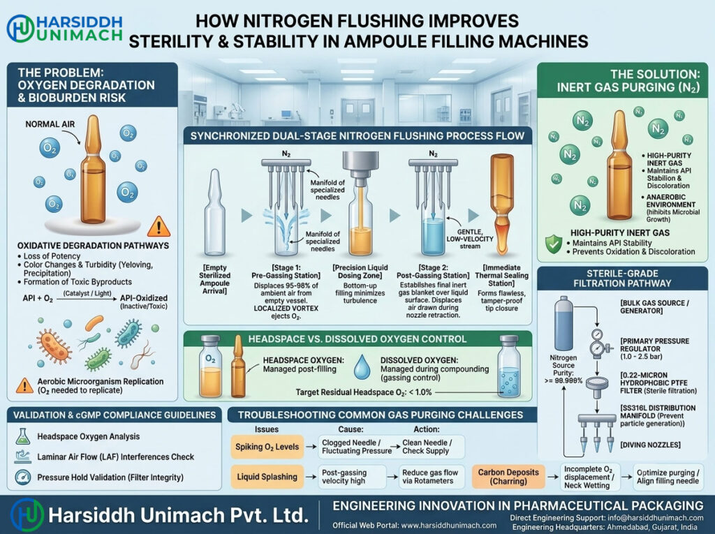
3. The Dual-Stage Nitrogen Flushing Process Flow
In high-speed production environments—such as the 8-head or 12-head automatic ampoule fillers designed by Harsiddh Unimach Pvt. Ltd.—relying on a single blast of gas is rarely enough to meet strict global regulatory standards. Instead, a synchronized, dual-stage purging process flow is used.
[Empty Sterilized Ampoule Arrival]
               │
               ▼
   [Stage 1: Pre-Gassing Station]
  (Displaces 95-98% of ambient air)
               │
               ▼
   [Precision Liquid Dosing Zone]
 (Bottom-up filling minimizes turbulence)
               │
               ▼
  [Stage 2: Post-Gassing Station]
 (Establishes final inert gas blanket)
               │
               ▼
 [Immediate Thermal Sealing Station]
Phase 1: Pre-Gassing (Pre-Filling Purging)
Before any liquid product enters the glass container, the empty ampoule moves via an eccentric transport rack to the pre-gassing station.
- The Operation: A manifold of specialized gas needles descends coaxially into the narrow open neck of the ampoule.
- The Mechanism: High-purity nitrogen gas is injected at a precisely controlled pressure and flow rate. This targeted stream creates a localized vortex that lifts and expels the heavier ambient air up and out of the neck.
- The Target: This step eliminates roughly 95% to 98% of atmospheric oxygen from the empty vessel, preparing a clean, inert environment for the incoming liquid.
Phase 2: Post-Gassing (Post-Filling Purging)
Immediately after the liquid dosing nozzles complete their cycle, the transport mechanism moves the filled ampoules to the post-gassing station.
- The Operation: A second set of nitrogen needles descends to fluid-head height.
- The Mechanism: A gentle, low-velocity stream of nitrogen gas is delivered across the liquid surface. This step is designed to displace any ambient air that may have been drawn into the container during nozzle retraction or fluid displacement.
- The Target: This stage establishes the final inert gas blanket over the product meniscus, ensuring that the residual headspace oxygen concentration remains under targeted limits (frequently less than 1.0%) right up to the moment of flame fusion.
4. Mechanical Engineering of Gas Manifolds in Harsiddh Unimach Equipment
To consistently achieve low residual oxygen levels at high production speeds (up to 12,000+ ampoules per hour), the underlying gas transport mechanics must be engineered with high precision. At Harsiddh Unimach Pvt. Ltd., our design methodology prioritizes laminar gas flow, structural cleanliness, and easy validation.
Fluid Dynamics and Nozzle Geometry
If nitrogen is delivered at too high a velocity, it can create a turbulent stream that draws outside air back into the ampoule neck, reversing the purging effect. Conversely, if the velocity is too low, it will fail to displace the ambient air.
Our systems use custom-tapered diving needles combined with independent micro-flowmeters (Rotameters) for each individual head. This layout allows validation engineers to fine-tune the gas delivery profile based on the specific shape and size of the ampoule being processed (1 ml to 20 ml).
Sterile-Grade Filtration Pathways
Because nitrogen gas comes into direct contact with the internal surfaces of the container and the sterile product itself, the gas supply line must match the cleanroom’s environmental parameters.
[Bulk Gas Source / Generator] ──► [Primary Pressure Regulator] ──► [0.22-Micron Hydrophobic PTFE Filter] ──► [SS316L Distribution Manifold] ──► [Diving Nozzles]
- Material Construction: All gas distribution blocks, pipe networks, valves, and needles are manufactured from Stainless Steel 316L, polished to a sanitary internal finish to prevent particle generation.
- Microbial Interception: A 0.22-micron hydrophobic PTFE sterile-grade gas filter is installed just upstream of the delivery manifold. This filter removes microscopic particulates, bacterial spores, and potential moisture droplets from the gas stream, ensuring that the nitrogen itself does not introduce contamination.
5. Technical Parameters for Gas Integration
To maintain stable cleanroom conditions, engineers track specific gas properties and operational metrics. The following profile represents a typical configuration for an advanced nitrogen flushing system:
| Parameter Requirement | Standard Engineering Value | Purpose / Significance |
| Nitrogen Source Purity | ≥99.999% | Minimizes trace oxygen impurities inside the supply line. |
| Delivery Pressure (Line) | 1.0 bar to 2.5 bar | Ensures a stable, regulated feed to the distribution rotameters. |
| Filtration Rating | 0.22 µm (Hydrophobic) | Provides sterile filtration, removing airborne microflora and fine particulates. |
| Target Residual Headspace $O_2$ | <1.0% (Optionally <0.5%) | Prevents oxidative degradation over long-term shelf storage. |
| Construction Specification | Stainless Steel 316L | Resists chemical cleaning agents and prevents internal line corrosion. |
6. Validation and cGMP Compliance Guidelines
In international pharmaceutical manufacturing, processes must be thoroughly documented and verified to meet current Good Manufacturing Practices (cGMP) enforced by regulatory bodies like the USFDA, MHRA, and WHO.
📋 Key Validation Protocols (SOPs)
- Headspace Oxygen Analysis: Production lines must undergo routine destructive and non-destructive testing using specialized headspace analyzers (such as laser-based frequency modulation spectroscopy). This testing verifies that the nitrogen system is consistently hitting its residual oxygen targets across all filling heads.
- Laminar Air Flow Interferences: Because ampoule filling machines run under Class 100 Laminar Air Flow (LAF) hoods, the upward exhaust velocity of the nitrogen gas must be carefully balanced. If the gas velocity is too high, it can disrupt the uniform downward flow of sterile cleanroom air, potentially creating localized turbulence zones.
- Pressure Hold Validation: The integrity of the sterile filter assembly must be verified before and after each production batch using an automated integrity tester (via Bubble Point or Pressure Decay methods) to confirm that no microbial penetration occurred through the filter medium.
7. Troubleshooting Common Gas Purging Issues
When setting up or optimizing an automated line, technical teams may encounter specific performance variations. This matrix outlines common challenges along with their root causes and standard solutions:
| Observed Phenomenon | Probable Technical Root Cause | Recommended Corrective Action |
| Spiking Residual Headspace O₂ Levels | 1. Clogged or misaligned diving gas needle. 2. Fluctuating incoming line pressure from the source. | 1. Remove and clean the needle tip; verify coaxial alignment with the ampoule center. 2. Check primary supply gauges and service the line regulators. |
| Liquid Splashing During Gassing | The post-gassing needle is diving too deep or the gas velocity is too high. | Adjust the mechanical stroke limiters on the diving manifold. Decrease the gas flow rate via the individual station rotameters. |
| Carbon Deposit Formations (Charring) | Incomplete oxygen displacement combined with product drops adhering to the neck wall. | Optimize both pre-gassing and post-gassing flow dynamics. Check and adjust the diving filling needle centering to eliminate neck wetting. |
| Premature Sealing Blisters/Deformations | Cold nitrogen gas causing uneven thermal cooling during flame pull-off. | Adjust the distance between the post-gassing manifold station and the pre-heating burners to allow a smooth thermal transition. |
8. Summary and Systems Engineering
Nitrogen flushing is more than a simple regulatory checklist item—it is a critical, high-precision step within the aseptic packaging workflow. By properly managing gas dynamics, integrating sterile-grade 0.22-micron filtration, and choosing high-quality mechanical configurations, pharmaceutical manufacturers can significantly reduce oxidation risks, eliminate aerobic microbial threats, and extend product shelf life.
At Harsiddh Unimach Pvt. Ltd., we construct high-speed liquid packaging systems that blend mechanical reliability with modern cleanroom compliance. Our engineering teams customize gas manifold structures, dosing controls, and automated sensors to align perfectly with your facility’s specific technical needs and validation requirements.
Connect with Our Engineering Division
To learn more about our advanced machinery configurations, request detailed layout blueprints, or schedule a custom validation consultation for your parenteral manufacturing line, please reach out through our official channels:
- Corporate Manufacturer: Harsiddh Unimach Pvt. Ltd.
- Engineering Headquarters: Ahmedabad, Gujarat, India
- Official Web Portal: www.harsiddhunimach.com
- Direct Engineering Support: info@harsiddhunimach.com