
In the modern pharmaceutical landscape, manufacturing flexibility is no longer just an operational advantage—it is a regulatory and commercial necessity. Gone are the days when a parenteral packaging line could be dedicated to a single product and container size indefinitely. Today, contract development and manufacturing organizations (CDMOs) and generic drug formulators must routinely switch production lines between varying container capacities, shifting from a 1 ml batch to a 5 ml or 10 ml run within the same week.
The bottleneck in this high-stakes environment is the machine changeover process. A poorly executed changeover directly penalizes Overall Equipment Effectiveness (OEE), introduces mechanical wear, and risks devastating cross-contamination or batch failure.
As a leading global authority in industrial liquid packaging, Harsiddh Unimach Pvt. Ltd. engineers high-speed automated ampoule filling lines with rapid-changeover architectures. This exhaustive guide provides an engineering-focused, step-by-step framework for managing the changeover process of an automatic ampoule filling and sealing machine across different container sizes while maintaining strict cGMP compliance.
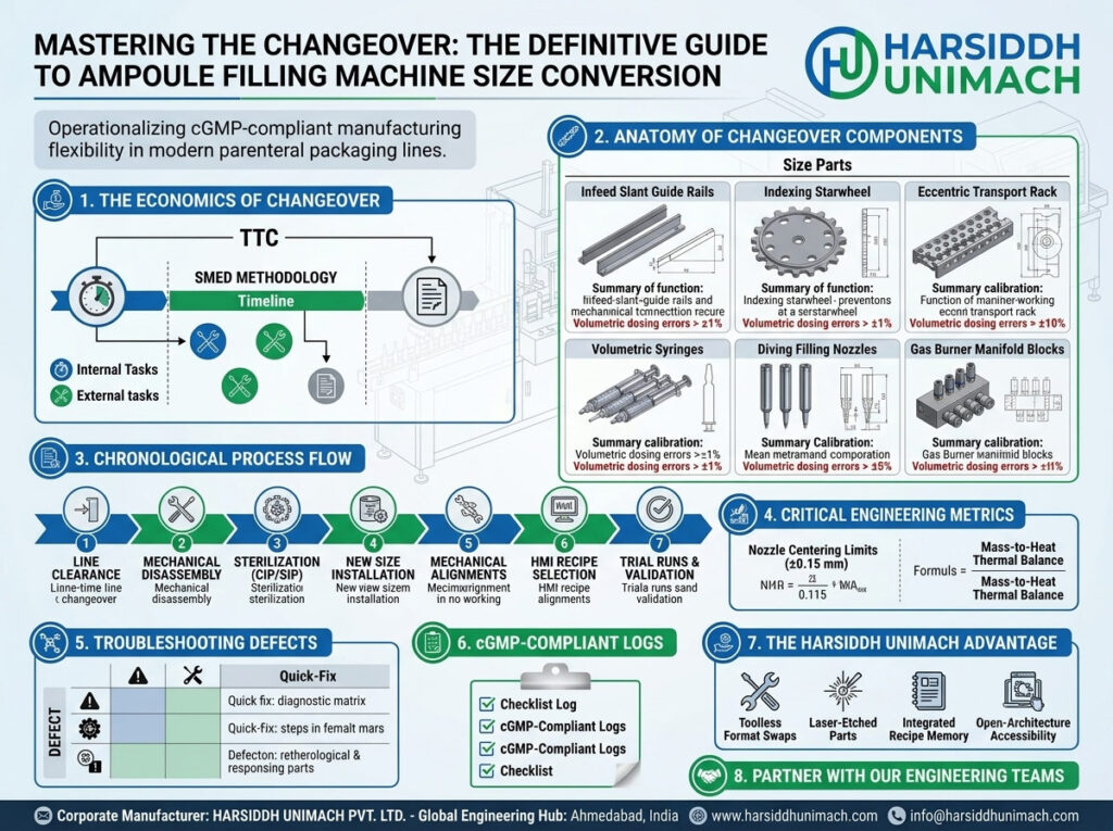
1. The Economics of Changeover: Balancing OEE and Flexibility
In a sterile filling suite, downtime is exceptionally costly. Every hour an ampoule line sits idle for format changes represents lost revenue, continuous cleanroom energy consumption, and labor overhead.
The primary goal of modern line management is to minimize the Total Time to Changeover (TTC). This is defined as the elapsed time between the last good container of Batch A and the first fully validated, sterile container of Batch B.
[Batch A Ends] ──► [Line Clearance & Sanitation] ──► [Mechanical Size Part Swap] ──► [Recipe & Calibration] ──► [Validation & First Good Vial]
                               ◄────────────────────────── Total Time to Changeover (TTC) ─────────────────────────►
Applying the SMED Methodology to Ampoule Lines
To optimize this workflow, Harsiddh Unimach implements the Single-Minute Exchange of Die (SMED) framework. SMED classifies changeover operations into two distinct classes:
- Internal Elements: Actions that can only be performed when the machine is completely stopped (e.g., swapping out the eccentric transport rack or removing volumetric syringes).
- External Elements: Actions that can be performed while the machine is actively running Batch A or after Batch B has commenced (e.g., pre-heating replacement syringes, pre-sorting size parts, or preparing batch documentation).
By shifting internal elements to external tasks through smart engineering—such as toolless quick-release mechanisms—advanced filling lines can reduce mechanical setup times by up to 60%.
2. Anatomy of Changeover Components (Size Parts)
When shifting from one ampoule volume to another, the dimensions of the glass change dramatically. A standard $1 \text{ ml}$ ampoule differs substantially from a $10 \text{ ml}$ or $20 \text{ ml}$ ampoule in overall height, body diameter, neck width, and wall thickness. Consequently, a specific set of mechanical “size parts” or “format parts” must be systematically swapped.
| Changeover Component | Functional Role in Size Conversion | Impact of Incorrect Calibration |
| Infeed Slant Guide Rails | Aligns varying glass diameters as they slide from the depyrogenation tunnel into the filler. | Ampoule bridging, jam-ups, or micro-fractures in the glass. |
| Indexing Starwheel / Scroll | Singulates and meters individual ampoules into the transport path. | Crushed containers, systematic indexing timing lag. |
| Eccentric Transport Comb/Rack | Advances groups of ampoules (e.g., 8 at a time) through functional stations. | Displaced centering under nozzles, scraping of glass walls. |
| Volumetric Syringes (Piston/Servo) | Calibrates the physical fluid displacement per mechanical stroke. | Volumetric dosing errors exceeding cGMP limits (±1%). |
| Diving Filling Nozzles | Penetrates the ampoule neck coaxially to drop the liquid payload. | Wetting of the neck wall, causing tip charring during sealing. |
| Gas Burner Manifold Blocks | Directs pre-heating and sealing micro-flames to the exact height of the neck. | Malformed tips, blowholes, or incomplete hermetic closure. |
3. Step-by-Step Chronological Changeover Process Flow
To eliminate human error and safeguard aseptic integrity, engineers must follow a rigid chronological sequence. Deviating from this protocol can lead to mechanical collisions upon startup.
[Step 1: Line Clearance] ──► [Step 2: Component Disassembly] ──► [Step 3: Sterilization & CIP/SIP]
                                                                        │
                                                                        ▼
[Step 6: Validation & Run] ◄── [Step 5: HMI & Servo Tuning] ◄── [Step 4: New Size Installation]
Step 1: Line Clearance and Safety Isolation
Before a single tool touches the machine, the current batch must be completely closed out.
- Clear all remaining processed ampoules from the outfeed collection tray.
- Purge and discard all leftover waste glass remnants from the clipper collector bins.
- Remove all remaining active labels, batch records, and product-specific materials from the room to avoid mislabeling cross-contamination.
- Shut down all gas utilities (LPG, Oxygen, and Nitrogen lines) and lock out/tag out (LOTO) the primary electrical drive circuit.
Step 2: Mechanical Disassembly of Batch A Components
Once the line is cleared, operators remove the product-contact and size-dependent components of the old batch format.
- Disconnect the liquid product feed lines from the manifold.
- Remove the dosing syringes and diving needles. Handle these with extreme care; SS316L polished piston pumps feature micro-inch tolerances, and minor drops can cause scoring or binding.
- Loosen the quick-release lock screws on the eccentric transport rack and slide the comb guides out of their tracking channels.
- Extract the infeed singulation starwheel and changeover scrolls.
Step 3: Cleaning, Decontamination, and Sterilization (CIP/SIP)
With the size parts removed, the bare machine chassis and the removed parts undergo meticulous decontamination.
- Product-Contact Components: Syringes, needles, and silicone tubes are transferred to a wash station for Clean-in-Place (CIP) or loaded into an autoclave for Sterilization-in-Place (SIP) processing to neutralize any active biological or chemical residues.
- Non-Contact Areas: The open-bottom SS304 frame and transport tracks are wiped down using validated sporicidal agents and Isopropyl Alcohol (IPA 70%).
Step 4: Installation of New Size-Specific Components
The operators retrieve the pre-validated size parts dedicated to the upcoming container size (e.g., transitioning to a 5 ml configuration).
- Slide the new infeed guide rails into position, adjusting the width settings to match the new body diameter using the machine’s integrated millimeter scale dials.
- Install the new indexing starwheel ensuring the pocket profile matches the glass radius snugly.
- Lock the new transport comb into place. Harsiddh Unimach machinery utilizes pin-positioning layouts, meaning parts drop into perfect alignment without requiring tedious manual adjustments.
- Mount the correct volumetric pumps. For example, if shifting from 1 ml to 5 ml, swap out the 1 ml micro-syringes for larger 5 ml or 10 ml calibrated pump blocks.
- Secure the new filling needles, ensuring their gauge (outer diameter) leaves sufficient clearance within the narrower internal diameter of the target ampoule necks.
Step 5: Mechanical Alignments and Utility Tuning
Because different ampoule sizes vary in height, all vertical workstations must be realigned.
                       ▲
                       │ Adjust Burner Assembly Height
                       ▼
    [ Burner Tip ] ──────────► [ New Ampoule Fusion Zone ]
                               [                         ]
                               [    New 5ml Ampoule      ]
                               [                         ]
- Burner Height Adjustment: Adjust the vertical position of the pre-heating and sealing gas burner manifold. The micro-flames must strike the ampoule neck precisely at the shoulder-to-tip transition zone. If the burner sits too low, it will boil the product fluid; if too high, it will leave a long, fragile glass hair tip.
- Clipper Stroke Calibration: Adjust the vertical and horizontal travel paths of the mechanical grippers. The clippers must grip the waste glass tip precisely as it transitions to a molten state, pulling it smoothly upward.
- Gas Flow Optimization: Adjust the rotameter values for Oxygen (O₂) and LPG. Larger glass volumes feature thicker walls, requiring increased thermal energy (higher gas flow) to achieve clean, uniform melting.
Step 6: HMI Recipe Selection and Electronic Calibration
Modern filling lines eliminate manual drive adjustments through advanced digital control architectures.
- Power up the main control system panel and navigate to the Human-Machine Interface (HMI) dashboard.
- Load the pre-saved digital recipe corresponding to the target ampoule size (e.g.,
RE_05ML_VAR01). - The integrated Programmable Logic Controller (PLC) automatically recalibrates the machine’s electronic parameters:
- Servo-Driven Indexing Speeds: Adjusts acceleration and deceleration profiles to account for the higher mass of filled 5 ml or 10 ml ampoules, preventing fluid sloshing.
- Dosing Stroke Velocity: Dynamically alters the piston profile to maximize fill speed while eliminating splashing.
- Nitrogen Purging Timing: Shifts the gas injection windows to match the adjusted mechanical index timeline.
Step 7: Trial Runs and Quality Validation Checks
Before releasing the line back to full production, a formal test run must be executed using sample glass components.
- Dry Cycle Run: Manually jog or slow-run the machine with a few empty ampoules to verify there is zero physical interference or friction across the starwheels, transport combs, and descending nozzles.
- Volumetric Calibration Verification: Perform a test fill using a placebo fluid (typically Water for Injection – WFI). Collect filled ampoules across all eight heads and weigh them on an analytical scale to calculate actual dosing accuracy:
Dosing Error (%) = |(Actual Mass − Target Mass) ÷ Target Mass| × 100
- Hermetic Seal Quality Check: Ignite the burners, run the sealing station, and inspect the finished dome tips under magnification. Check for cosmetic flaws like pinholes, charring, or uneven glass distribution.
4. Critical Engineering Metrics for Flawless Conversions
To maintain structural consistency during setups, calibration technicians should track several critical metrics:
Nozzle Centering Limits
The diving filling needles must descend along the exact coaxial center line of the glass neck. The allowable deviation limit is extremely tight:
Allowable Radial Eccentricity ≤ ±0.15 mm
If the needle shifts further from center, the liquid droplet will touch the inner neck wall, leading to immediate carbonization (black char spots) during flame contact.
Mass-to-Heat Thermal Balance
The volume of glass in an ampoule neck scales non-linearly with container volume. When executing a changeover, look up the validated gas pressure values in your machine documentation:
- Small Sizes (1ml – 2ml): Lower gas pressure, sharper flame focus to prevent shoulder melting.
- Large Sizes (10ml – 20ml): Wider flame spread, higher thermal output to ensure complete glass fusion within the brief dwell window of the indexing cycle.
5. Troubleshooting Post-Changeover Defects
If production anomalies arise immediately following a format swap, use this diagnostic matrix to pinpoint and resolve the underlying issue:
| Production Defect | Likely Mechanical Root Cause | Target Correction Step |
| Systematic Glass Cracking at Infeed | The singulation scroll or starwheel is pinching the glass against the guide plates. | Loosen the starwheel mounting plate; check for correct part number matching for that container size. |
| Long Tail / Hair-Tip Formation | 1. Sealing burner position is too high. 2. Clipper vertical pull speed is too slow. | 1. Lower the burner manifold assembly via the mechanical handwheel. 2. Increase the pneumatic pressure or adjust servo timing for the clipper stroke. |
| Liquid Splashing Out of Neck | Syringe plunger velocity profile is too aggressive for the larger liquid volume. | Access the HMI pump control screen and decrease the primary fill speed profile while increasing the deceleration dampening window. |
| Cloudy / Carbonized Tips | Product droplets are clinging to the neck wall due to poor nozzle alignment or dripping. | Re-center the needle manifold assembly. Check and adjust the pump’s suck-back mechanism setting to eliminate tip dripping. |
6. Checklist for cGMP-Compliant Changeover Logs
Every changeover must be formally recorded to comply with international regulatory audits (such as USFDA or MHRA). A standard engineering log should verify and document the following items:
- [ ] Line Clearance Certification: Confirmed signed off by Quality Assurance (QA).
- [ ] Part Number Match Verification: Verified that all installed size parts display the correct laser-etched identification codes for the target container size.
- [ ] Calibrated Tool torque verification: Confirmed all structural quick-release levers and fasteners are securely locked down.
- [ ] Heads Centering Inspection: Confirmed all eight diving needles descend smoothly without striking any glass surfaces.
- [ ] Gas Integrity Pressure Check: Verified that line pressures for Oxygen, LPG, and Nitrogen align with validated recipe parameters.
- [ ] Dosing Weight Verification Report: Printed and signed data sheet demonstrating ≤ ±1% volumetric variance across all fill ports.
7. The Harsiddh Unimach Advantage in Line Flexibility
At Harsiddh Unimach Pvt. Ltd., we design our machinery with a deep understanding of the challenges operators face on the production floor. Our automated filling and sealing systems eliminate the traditional frustrations of format changes through several key design features:
- Toolless Format Swaps: Our size parts utilize quick-clamping handles and click-in locator pins, removing the need for complex hand tools and drastically shortening internal changeover windows.
- Laser-Etched Component Part Numbers: Every size part is permanently engraved with its unique configuration code, helping setup technicians easily identify and organize components.
- Integrated Recipe Memory: Our intelligent PLC control platforms store up to 100 distinct product and size profiles, allowing operators to execute complex electronic and servo re-calibrations at the touch of a button.
- Open-Architecture Accessibility: The spacious structural layout of our machines allows operators clear, unobstructed access to all internal sub-assemblies, making cleaning, sterilization, and part swap adjustments safe and straightforward.
8. Summary and Technical Procurement
Optimizing the changeover process for different ampoule container sizes is an effective way to boost production efficiency and enhance the agility of your manufacturing facility. By implementing systematic workflows, leveraging SMED best practices, and investing in modern, flexible machinery architectures, pharmaceutical packagers can significantly reduce operational downtime, safeguard batch sterility, and drive up overall line profitability.
Partner with Our Engineering Teams
If you are looking to update your current parenteral production capabilities, upgrade old machinery with high-efficiency quick-change conversions, or integrate an advanced, high-speed multi-format filling line into your facility, please connect with the technical division at Harsiddh Unimach Pvt. Ltd. Our international application engineers are ready to design a solution tailored to your exact operational and compliance goals.
- Corporate Manufacturer: Harsiddh Unimach Pvt. Ltd.
- Global Engineering Hub: Ahmedabad, Gujarat, India
- Official Web Domain: www.harsiddhunimach.com
- Direct Engineering Support: info@harsiddhunimach.com