
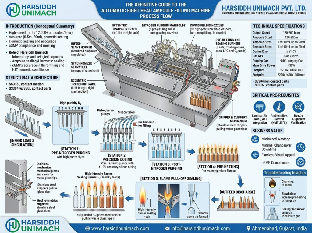
In large-scale pharmaceutical manufacturing, achieving sterility, accurate dosing, and high-speed throughput is paramount. Liquid injectables require an uncompromisingly sterile environment and hermetic sealing to preserve drug efficacy and guarantee patient safety. At the center of modern parenteral production lines sits the Automatic Eight Head Ampoule Filling and Sealing Machine.
Engineered for high-volume operations, an 8-head system bridges the gap between precision engineering and strict compliance with Current Good Manufacturing Practices (cGMP). This comprehensive guide provides an in-depth analysis of the operational architecture, step-by-step process flow, critical technical parameters, and optimization strategies for the automatic eight-head ampoule filling machine.
1. Introduction to the Eight Head Ampoule Filling Machine
An automatic eight-head ampoule filling and sealing machine is an integrated system designed to process glass ampoules (both open-mouth and closed-mouth varieties) concurrently in groups of eight. By synchronizing mechanical, pneumatic, and electronic sub-assemblies, this machine delivers high-speed performance without sacrificing volumetric precision.
The Role of Harsiddh Unimach Pvt. Ltd.
As a premier engineering entity in industrial packaging, Harsiddh Unimach Pvt. Ltd. designs and manufactures state-of-the-art liquid processing lines. Our specialized 8-head configurations are engineered to handle structural variations in glass ampoule necks, ensuring high reliability, zero cross-contamination, and seamless integration into sterile cleanrooms or beneath Laminar Air Flow (LAF) hoods.
Key Performance Capabilities
- Throughput Efficiency: Processes up to 12,000 ampoules per hour (varying between 120 to 200 ampoules per minute depending on fill volume and liquid viscosity).
- Versatile Dosing Range: Accurately dispenses volumes spanning from 0.5 ml to 20 ml utilizing specialized pump configurations.
- Hermetic Integrity: Utilizes a dual-stage flame system (pre-heating and pull-off sealing) to deliver flawless, tamper-proof tip closures.
2. Structural Architecture and Essential Components
To understand the process flow, one must first understand the structural engineering that supports it. Every machine built by Harsiddh Unimach Pvt. Ltd. features a precise architectural layout to preserve a sterile path for product handling.
Stainless Steel Chassis and Enclosures
- Contact Parts (SS316L): All components coming into direct contact with the liquid injectable—such as filling needles, manifold blocks, and volumetric syringes—are manufactured from Stainless Steel $316L$. This material exhibits high resistance to chemical corrosion and withstands rigorous Cleaning-in-Place (CIP) and Sterilization-in-Place (SIP) cycles.
- Non-Contact Parts (SS304): The outer paneling, structural framing, and internal mechanical beds are constructed from Stainless Steel 304 featuring a premium matt finish. The machine base is designed with an open-bottom structural layout to facilitate absolute cleaning, fluid drainage, and air circulation.
Detailed Component Overview
| Component Name | Primary Engineering Function |
| Infeed Slant Hopper | Receives sterilized, empty ampoules from a depyrogenation tunnel and aligns them into a single-file stream. |
| Synchronized Starwheel | A rotary indexing device that segments the continuous feed of ampoules into precise groups of eight. |
| Eccentric Transport Rack | A specialized, inclined comb/rack system that advances eight ampoules per cycle in a left-to-right slant travel motion. |
| Nitrogen Purging Manifolds | Houses sixteen individual gas nozzles split evenly between pre-filling and post-filling stations to displace atmospheric oxygen. |
| Diving Filling Nozzles | Eight high-precision needles that descend coaxially into the ampoule necks to drop the liquid without wetting the upper walls. |
| Volumetric Pumps / Syringes | Mechanical dosing units (piston, servo, or peristaltic) that calibrate the precise fluid displacement per stroke. |
| Pre-Heating & Sealing Burners | Gas manifolds feeding LPG and Oxygen (O₂) mixtures to create precise, focused micro-flames. |
| Grippers / Clippers Mechanism | Mechanical scissors that pull away the waste glass tip during the molten phase of the sealing operation. |
3. Step-by-Step Process Flow of an 8-Head Ampoule Filler
The operational workflow of the automatic eight-head ampoule filling machine relies on a stop-start index sequence. While the transport rack is in horizontal motion, the ampoules shift to the next functional zone; when the rack comes to a momentary halt, all eight heads at every station simultaneously execute their designated tasks.
[Infeed Hopper & Starwheel Alignment]
                  │
                  ▼
   [Station 1: Pre-Nitrogen Purging]
                  │
                  ▼
    [Station 2: Precision Dosing]
                  │
                  ▼
  [Station 3: Post-Nitrogen Purging]
                  │
                  ▼
      [Station 4: Pre-Heating]
                  │
                  ▼
   [Station 5: Flame Pull-Off Sealing]
                  │
                  ▼
     [Outfeed & Collection Tray]
Step 1: Infeed Loading and Starwheel Singulation
The process begins immediately after the ampoules exit the washing unit and depyrogenation tunnel.
- Sterilized, cooled glass ampoules are loaded directly into the machine’s Infeed Slant Hopper.
- The ampoules slide down via gravity toward a Synchronized Starwheel (or cassette device).
- This starwheel segments and indexes the ampoules, placing them in sets of eight onto the Moving Eccentric Transport Rack.
- The rack carries the ampoules in an inclined position at a set angle. This slant-travel mechanism accounts for variations in ampoule neck diameter and wall thickness, ensuring identical positioning across all cycles.
Step 2: Pre-Gassing / Pre-Nitrogen Flushing
Oxygen is a primary agent of degradation for many pharmaceutical formulations, especially sensitive vitamins, antibiotics, and biologics.
- Once the rack advances the eight ampoules to the first process station, it pauses.
- Eight Pre-Nitrogen Nozzles descend into the open necks.
- An inert gas layer (typically high-purity Nitrogen) is flushed into the empty ampoule at a controlled flow rate regulated by integrated flow meters.
- This action displaces ambient oxygen, moisture, and atmospheric gases, establishing an inert headspace.
Step 3: Precision Liquid Dosing (The Filling Station)
This is the most critical stage within the process flow. To ensure that expensive formulations are not lost, the machine achieves a high dosing accuracy of ±1%.
- The Diving Motion: The eight filling nozzles descend deep into the narrow neck of the ampoules. This bottom-up approach ensures the needle tip penetrates past the sealing zone before liquid delivery begins.
- Elimination of Neck Contact: The nozzles are centered during the descent. If the liquid touches the inside wall of the neck, it can cause charring (black carbon specs) or cracking during the subsequent flame sealing process.
- Fluid Displacement: The designated pump type delivers the set volume:
- Piston Pumps: Ideal for high-speed, repetitive volumetric consistency.
- Servo-Driven Systems: Allow users to adjust filling profiles dynamically via an HMI panel.
- Peristaltic Pumps: Ensure total sterility, as the product only makes contact with medical-grade silicone tubing.
- “No Ampoule – No Filling” Protocol: Proximity sensors scan the transport slot. If one of the eight slots is missing an ampoule, the corresponding pump is pneumatically or electronically isolated, preventing product discharge and saving material.
Step 4: Post-Gassing / Post-Nitrogen Flushing
Immediately after fluid delivery, the filling nozzles retract, and the rack shifts the ampoules to the post-gassing station.
- Eight Post-Nitrogen Nozzles descend into the filled ampoules.
- A second blast of nitrogen gas flushes out any oxygen that entered the container during the liquid filling phase.
- This locks an inert gas blanket over the liquid meniscus, extending the product’s shelf life and stability.
Step 5: The Two-Stage Sealing Operation
Sealing converts the open glass vessel into an airtight, sterile ampoule via a thermal fusion process.
- Stage A: Pre-Heating: The filled ampoules advance to the pre-warming station. Here, medium-intensity flames fed by LPG and Oxygen (O₂) envelop the necks. Specialized rollers rotate the ampoules continuously to deliver a uniform 360° heat distribution. This stage drives away any micro-droplets of condensation or product residue clinging to the inner glass wall before final closure.
- Stage B: Flame Pull-Off Sealing: The ampoules slide to the final sealing zone where they face intense, high-temperature micro-flames. As the glass neck reaches its molten, plasticized state, a synchronized mechanism of Stainless Steel Clippers (or Grippers) grabs the top waste portion of the glass neck and pulls it vertically upward. The flame melts and rounds off the top of the remaining glass tube, forming a smooth, hermetic dome tip.
Step 6: Outfeed Discharge and Finished Product Collection
The waste glass tips pulled off by the clippers fall down a collection chute into a scrap bin. Concurrently, the fully sealed, hot ampoules are pushed by the advancing transport rack out of the inclined guide rails. They slide gently onto an automated Stainless Steel Outfeed Collection Tray without any direct manual intervention, preserving complete batch sterility.
4. Technical Specifications and Operational Bounds
To configure the machine for optimal efficiency across different production lines, engineers utilize specific mechanical and electrical tolerances. The standard profile for an enterprise-grade 8-head system (Model AFS-200 / AFS-8) includes the following parameters:
| Technical Variable | Operational Metric / Limit |
| Production Output Speed | 120 to 200 ampoules per minute (Up to 12,000/hr) |
| Compatible Ampoule Sizes | From 1 ml to 10 ml (Adaptable up to 20 ml) |
| Dosing Precision Error | ≤ ±1.0% of targeted volume |
| Combustible Gas Mix | Liquid Petroleum Gas (LPG) & Compressed Oxygen (O₂) |
| Purging Gas | Industrial-Grade Gaseous Nitrogen (N₂) |
| Main Drive Mechanical Power | 1.5 HP to 2.0 HP Induction Motor |
| Electrical Interface | 230 V, Single Phase / 440 V, 3-Phase, 50 Hz Systems |
| Approximate System Footprint | 2200 mm (L) × 1400 mm (W) × 1100 mm (H) |
5. Critical Pre-Requisites for Aseptic Operations
Operating an automatic 8-head ampoule processing system within a pharmaceutical facility requires strict adherence to cleanroom validation protocols.
⚠️ Crucial Standard Operating Guidelines (SOPs)
- Laminar Air Flow Integration: The filling and sealing module must be operated under an active Laminar Air Flow (LAF) hood. Differential pressure across the system must be checked using a calibrated Magnehelic Gauge to ensure continuous downward Class 100 sterile air filtration.
- Ambient Environment Controls: The temperature within the aseptic filling enclosure must be maintained Not More Than (NMT) 25°C to protect the integrity of cold-chain biologics and ensure comfortable operating conditions for handling gas lines.
- Nozzle Alignment Verification: Operators must verify that the filling nozzles do not come into mechanical contact with the glass tips during entry. Friction can generate microscopic glass particulate matter, contaminating the batch. Nozzle centering should be verified using a vernier caliper or dedicated dial test gauges before starting the run.
6. Business Value and Advantages for Pharmaceutical Formulators
Investing in an automatic eight-head system from Harsiddh Unimach Pvt. Ltd. offers several key advantages for manufacturing plants:
- Minimized Wastage Profiles: The integrated “No Ampoule – No Filling” sensor loop eliminates fluid spillages, protecting valuable active pharmaceutical ingredients (APIs).
- Minimal Tool Changeover Downtime: The machine is designed with quick-release components. Changing the assembly setup from a 1 ml to 10 ml batch requires minimal changeover parts, reducing operational downtime between product batches.
- Flawless Visual Appeal: The combination of an integrated pre-warming station and a 360° rotating sealing station removes cosmetic defects such as black spots, blowholes, or uneven tip shapes, helping batches pass strict automated visual inspection stations.
- Full cGMP Compliance: With an open frame made of SS316L fluid pathways and high-grade safety guards, the equipment aligns with global regulatory standards, including USFDA and MHRA criteria.
7. Troubleshooting Common Production Challenges
| Observation | Probable Root Cause | Recommended Remedial Action |
| Charring / Black Specks at the Tip | Fluid deposition on the upper neck walls; incorrect nozzle centering. | Re-center the diving needle manifold. Adjust pump stroke settings to prevent post-fill dripping. |
| Formation of Blowholes / Pinholes | Insufficient pre-heating; residual moisture inside the neck glass walls. | Increase the pre-heating flame intensity using the integrated flow meters. Check the rotation speed of the ampoule rollers. |
| Dosing Variances ($> \pm 1\%$) | Air bubbles in the product manifold line; worn piston syringe seals. | Purge the air out of the silicone product lines before starting the run. Inspect and replace worn Teflon pump seals. |
| Incomplete Sealing / Flat Tips | Distorted gas pressure balance between LPG and O₂ clipping speed mismatch. | Re-calibrate the gas pressure reducers. Check for clogging in the burner tips and clean them. |
8. Summary and Ordering Information
The Automatic Eight Head Ampoule Filling and Sealing Machine is an essential asset for modern parenteral operations, combining high-speed output with precise fluid control and robust sterility. By automating everything from gassing to thermal sealing, it allows pharmaceutical facilities to minimize contamination risks and scale up batch capacities efficiently.
Get in Touch with Our Engineering Experts
For custom configurations, pricing detail sheets, and integration advice with your existing depyrogenation lines, contact Harsiddh Unimach Pvt. Ltd. directly. Our international engineering teams are ready to help you optimize your production output.
- Corporate Manufacturer: Harsiddh Unimach Pvt. Ltd.
- Official Web Domain: www.harsiddhunimach.com
- Direct Inquiry Email: info@harsiddhunimach.com