
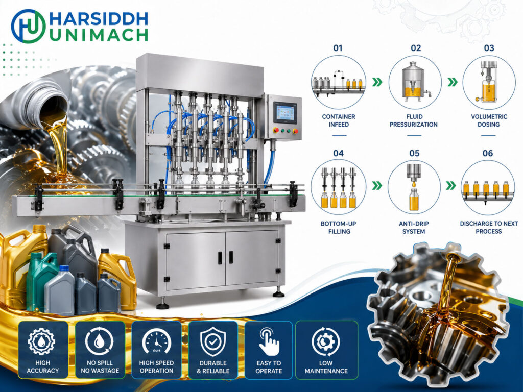
Gear oils protect the gears, bearings and differentials in vehicles, tractors, motorcycles and industrial gearboxes. Compared with engine oils, many gear oils are heavier and more viscous, and some contain additive packages designed for extreme-pressure conditions. They are sold in bottles with long spouts for easy topping up, in cans and buckets for workshops, and in larger containers for industry.
Heavy oils bring their own filling challenges: they flow slowly, cling to everything, form long strings at the nozzle and trap air bubbles that rise slowly. A gear oil filling machine is designed around these challenges. In this article, we explain how gear oil fillers work, how they handle high viscosity, which pumps and nozzles are used, how temperature helps, which containers are filled and how to set up and troubleshoot the line.
For lighter engine oils and general lubricant lines, see our engine oil filling machine working principle.
Why Gear Oil Is Harder to Fill
| Challenge | Why It Happens | Effect on Filling |
|---|---|---|
| High viscosity | Heavy base oils and additives | Slow flow, long fill times, pumps may not fill fully |
| Strong temperature effect | Viscosity rises sharply when cold | Fill variation and very slow filling in cold conditions |
| Stringing | Thick oil holds together | Long tails at the nozzle, drips on containers |
| Slow air release | Bubbles rise slowly through thick oil | Air pockets, foam on the surface, apparent underfill |
| Additive chemistry | Extreme-pressure and other additives | Seals and materials must be compatible |
| Slippery residues | Oil on necks and surfaces | Caps slipping, leaks, labels peeling |
For a general look at thick liquids, read our high viscous liquid filling machine working principle.
The Core Working Principle
Gear oil fillers use positive displacement or weight-based filling, because gravity filling is far too slow and inconsistent for heavy oils.
Servo gear pump filling
A servo motor drives a gear pump. The meshing gears carry oil from the inlet to the outlet in a smooth, continuous flow. Fill volume is set by the number of revolutions. Gear pumps are often the first choice for gear oils because:
- They handle high viscosities well
- The oil lubricates the pump itself
- Flow is smooth, reducing splashing and air entrapment
- Volume changes are made on the control panel
See the Automatic Servo Based Gear Pump Filling Machine and the servo based gear pump filling machine.
Servo piston filling
A servo-driven piston draws oil into a cylinder and pushes it out. Fill volume is set by the programmed stroke. For heavy oils, the suction stroke is slowed so the cylinder fills completely. Pistons are accurate and suit small and medium bottles.
See the servo based piston filling machine.
Weight filling
For buckets and larger cans, weight filling measures the oil directly with a load cell. It is unaffected by viscosity and temperature, making it reliable for heavy oils in large containers.
Designing for High Viscosity
Large passages
Valves, manifolds and pipework with large, smooth internal passages reduce resistance and pressure drop. Narrow passages make heavy oil flow slowly and strain pumps.
Feeding the pump
Heavy oil may not flow into the pump quickly enough under gravity alone. Solutions include:
- Positioning the supply tank above the pumps for good inlet head
- Short, wide inlet lines
- Slower suction strokes on piston fillers
- Feed pumps for large systems
Large-bore nozzles
Bigger nozzle bores keep fill times reasonable. For bottles with narrow necks, nozzles are sized as large as the neck allows.
Positive shut-off
Gear oil strings badly. Positive shut-off nozzles close right at the tip, cutting the oil cleanly. Combined with a short suck-back and a drip tray, they keep containers clean.
The Role of Temperature
The viscosity of gear oil rises sharply as temperature falls. In cold conditions, filling becomes slow and fills may vary. Many plants therefore:
- Store oil in a temperature-controlled area before filling
- Use heated or insulated supply tanks to keep oil at a consistent temperature
- Avoid overheating, which could affect product properties
- Check fills more frequently when temperatures change through the day
The right filling temperature should be agreed with the oil formulator and quality team. For very thick products, the principles in our paste filling machine working principle also apply.
Gear Oil vs Engine Oil Filling
| Aspect | Engine Oil | Gear Oil |
|---|---|---|
| Typical viscosity | Lighter to medium | Medium to heavy |
| Fill speed | Faster | Slower; needs speed profiles |
| Air release | Relatively quick | Slow; settling time may be needed |
| Temperature effect | Noticeable | Often very pronounced |
| Nozzle bore | Standard | As large as the neck allows |
| Common packs | Bottles, cans | Spout bottles, cans, buckets |
| Preferred dosing | Gear pump, piston, weight | Gear pump, weight; piston with slow suction |
Many lubricant plants fill both on the same line. The key is to store separate recipes for each grade, with suitable speed profiles, nozzle depths and settling times, and to flush the system between products.
Step-by-Step Filling Process
- Container feeding – bottles are fed upright by a bottle unscrambler; cans and buckets are loaded by an infeed or manually.
- Positioning – gates and guides place containers under the nozzles.
- Nozzle entry – nozzles enter the necks; for heavy oils, nozzles may dive deeper to start filling low and reduce air entrapment.
- Slow start – the pump starts gently until the nozzle tip is submerged.
- Main fill – flow increases to the maximum rate the product and container allow.
- Slow finish – flow slows as the target approaches, reducing surge and splashing.
- Cut-off – positive shut-off closes, suck-back pulls back the last drops and the drip tray swings in.
- Settling – where needed, a short dwell lets air bubbles rise before capping.
- Release – containers move to capping and sealing.
Gear Oil Packs
| Pack | Typical Use | Filling Notes |
|---|---|---|
| Small spout bottles | Motorcycles, top-up | Accurate small volumes, careful nozzle alignment |
| Medium bottles | Vehicles, tractors | Gear pump or piston filling |
| Cans | Workshops | Gear pump or weight filling |
| Buckets | Industrial gearboxes, fleets | Weight filling |
Bottles with long spout caps need capping equipment that can handle tall closures. Simpler screw caps can be applied by an inline capper such as the linear capping machine or, for small batches, the semi-automatic screw capping machine.
Gear Oil Filling Machines from Harsiddh
- Automatic Gear Oil Filling Machine
- Automatic Lubricant Oil Filling Machine
- Automatic Servo Based Oil Filling Machine
- Automatic Viscous Liquid Filling Machine
- Servo based oil and viscous filling machine
Browse all our liquid filling machines.
Completing the Line
After filling and capping, gear oil packs typically pass through:
- Induction sealing – a foil seal for leak protection and tamper evidence, using an induction sealing machine
- Labelling – on a bottle sticker labeling machine or other labeling machines for round bottles
- Batch coding, cartoning and palletising
Clean, oil-free bottle surfaces are essential for reliable sealing and labelling.
Checking Fill Accuracy
Heavy oils are usually checked by weight. Where the label declares volume, the weight is converted using the oil’s density at the filling temperature, and each grade needs its own value. Good practice includes:
- Checking every head at start-up and after each grade change
- Repeating checks at defined intervals, especially as temperatures change
- Allowing foam to settle before judging fill level visually
- Using in-line checkweighers on higher-volume lines
- Recording and trending results
Always follow the packaging and labelling regulations that apply in your market.
Changeover Between Grades
Changing from one gear oil to another, or between gear oil and engine oil, involves draining the supply tank and lines, flushing the pumps and nozzles, recalling the correct servo recipe, adjusting nozzles and guides for the next pack, and checking the first containers. Because heavy oils drain slowly, allowing enough time for draining, or using dedicated tanks for frequently run grades, reduces carry-over and waste.
Key Settings and Their Effects
| Setting | What It Controls | Effect If Wrong |
|---|---|---|
| Oil temperature | Viscosity | Slow filling, fill variation |
| Suction speed (piston) | Complete cylinder fill | Air in dose, light fills |
| Speed profile | Flow into container | Air entrapment, splashing, long fill time |
| Nozzle depth | Where filling starts | Foam and bubbles if too shallow |
| Shut-off and suck-back | Clean cut-off | Long strings, oily necks |
| Settling time | Air release | Foam on surface, false underfill |
| Fill volume, revolutions or weight | Dose | Under- or overfilling |
Troubleshooting Common Problems
| Problem | Likely Cause | Corrective Action |
|---|---|---|
| Very slow filling | Cold oil, small nozzles, narrow passages | Control temperature, enlarge nozzle within neck limits |
| Light fills | Pump not filling fully, air in oil | Slow suction, improve inlet head, allow air release |
| Long strings and drips | Weak shut-off | Positive shut-off nozzles, adjust suck-back |
| Foam or bubbles on surface | Fast filling, shallow nozzle | Dive nozzle deeper, slow start, add settling time |
| Leaking packs | Oil on neck, low torque | Improve drip control, check torque and sealing |
| Swollen seals | Incompatible materials | Use seals compatible with the oil and additives |
| Fill drift through the day | Temperature change | Stabilise temperature, check fills more often |
Safety and Housekeeping
Heavy oils make floors and machine surfaces slippery and are hard to clean once spread. Keep the filling area safe and tidy by using drip trays, fixing leaks promptly, cleaning spills immediately with suitable absorbents, and storing bulk oil and finished packs according to site rules. Operators should wear suitable protective equipment, and guards and emergency stops must always be in working order. A clean area also keeps containers free of oil, which helps capping, sealing and labelling.
Planning Output
Because heavy oils fill more slowly than lighter products, plan line capacity around realistic fill times for your heaviest grades and largest packs. Adding filling heads, using larger nozzles where necks allow, and keeping oil at a stable, suitable temperature are the main ways to raise output without compromising accuracy or cleanliness.
Maintenance Tips
- Inspect gear pumps and pistons regularly; heavy oils and additives can accelerate wear.
- Check seals and hoses for compatibility and condition.
- Keep nozzles clean and shut-off mechanisms working smoothly.
- Maintain heating and insulation on tanks and lines.
- Keep the filling area clean and free of oil for safety.
- Verify fill accuracy at start-up and at regular intervals.
How to Choose a Gear Oil Filling Machine
- Viscosity range of the oils to be filled
- Temperature control needs
- Pack types and sizes – spout bottles, cans, buckets
- Dosing technology – servo gear pump, piston or weight
- Nozzle and shut-off design for heavy oils
- Output and number of heads
- Material compatibility with additives
- Downstream integration – capping, sealing, labelling
Frequently Asked Questions
What is the working principle of a gear oil filling machine? It uses a servo gear pump, piston or weight filling system to deliver a measured dose of heavy oil through large-bore, positive shut-off nozzles into each container, with speed profiles to reduce air and splashing.
Why are gear pumps popular for gear oil? They handle high viscosities, deliver smooth flow, are lubricated by the oil itself and allow quick volume changes.
How does temperature affect gear oil filling? Gear oil becomes much thicker when cold, slowing filling and affecting accuracy. Temperature control keeps filling consistent.
How do you stop gear oil from stringing? Use positive shut-off nozzles, suck-back and drip trays.
Can the same machine fill engine oil and gear oil? Often yes, with suitable settings, nozzles and flushing between products.
Need a filling machine for heavy lubricants? Contact our team or send an inquiry with your oil grades, pack sizes and output targets.