
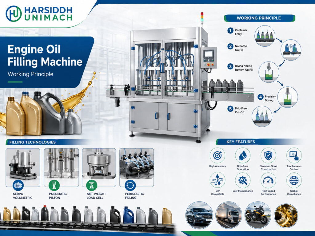
Engine oils and lubricants keep vehicles, motorcycles, tractors, generators and industrial machinery running smoothly. They are sold in a wide range of packs: small bottles for two-wheelers, one-litre bottles, multi-litre cans for cars, buckets for workshops and drums for fleets. Every pack must contain the declared quantity, look clean and professional, and be sealed so that it does not leak in transit or on the shop shelf.
An engine oil filling machine is designed to fill lubricants accurately and cleanly across different viscosity grades and pack sizes. In this article, we explain how engine oil fillers work, how viscosity and temperature affect filling, which dosing technologies are used, how bottles and cans are handled, and how the filler fits into a complete lubricant packing line.
How Engine Oil Behaves During Filling
| Property | Effect on Filling |
|---|---|
| Viscosity grade | Ranges from relatively thin to thick depending on the grade |
| Temperature sensitivity | Viscosity changes noticeably with temperature |
| Stringing | Oil forms strings at the nozzle at cut-off |
| Slipperiness | Oil on necks causes caps to slip and labels to fail |
| Additives | Some formulations contain additive packages that require compatible seals and materials |
| Low foaming | Most oils foam little, but splashing should still be avoided |
Because a single plant may fill many grades, from lighter multigrade oils to heavier gear and transmission oils, the filler must handle a range of viscosities without long adjustments. For heavier gear oils, see our gear oil filling machine working principle. For thick liquids in general, read our high viscous liquid filling machine working principle.
The Core Working Principle
Engine oil fillers use positive displacement or weight-based filling. The three main technologies are:
1. Servo gear pump filling
A pair of meshing gears, driven by a servo motor, carries oil from the inlet to the outlet. Fill volume is set by the number of pump revolutions. Gear pumps are well suited to lubricants because the oil itself lubricates the gears, flow is smooth, and the volume can be changed instantly from the control panel. This makes them popular for multi-grade, multi-pack lines.
See the servo based gear pump filling machine.
2. Servo piston filling
A servo-driven piston draws oil into a cylinder and pushes it out through the nozzle. Fill volume is set by the programmed stroke. Piston fillers give consistent volumes across a wide viscosity range and suit small and medium bottles.
See the servo based piston filling machine.
3. Weight filling
The container sits on a load cell while oil flows in, with a fast fill followed by a slow top-up. Filling stops at the target weight. Weight filling compensates automatically for temperature and density changes and is common for larger cans, buckets and drums.
For a deeper comparison, read weight-based vs volumetric filling.
| Technology | Dose Controlled By | Best For |
|---|---|---|
| Servo gear pump | Revolutions | Multi-grade lines, bottles and cans, quick changeovers |
| Servo piston | Stroke | Small and medium bottles, high accuracy |
| Weight filling | Load cell | Large cans, buckets, drums |
Main Components of an Engine Oil Filling Machine
- Supply tank – holds oil above or beside the filler, with level control
- Filling pumps – servo gear pumps or pistons, one per head
- Manifold and valves – distribute oil to each nozzle
- Anti-drip nozzles – positive shut-off to stop strings and drips
- Conveyor – carries bottles or cans through the machine
- Gates or indexing system – positions containers under the nozzles
- Load cells (weight fillers) – weigh each container
- Drip tray – swings under nozzles between fills
- Control panel (HMI) – sets volume, speed and recipes for each grade and pack
Step-by-Step Filling Process
Step 1: Container feeding
Empty HDPE bottles are fed upright onto the conveyor, usually by a bottle unscrambler. Larger cans and buckets are often loaded manually or by a dedicated infeed.
Step 2: Positioning
Gates hold a group of containers under the nozzles. Because many lubricant bottles are flat or oval with an offset neck, guides must position the neck precisely under each nozzle.
Step 3: Nozzle entry
Nozzles descend into the container necks. Entering the neck stops oil from running down the outside of the bottle.
Step 4: Filling
The pumps deliver the dose. Servo speed profiles, slower at the start and end, faster in the middle, reduce splashing and give a clean finish.
Step 5: Cut-off and drip control
Positive shut-off nozzles close at the tip, and a brief suck-back can draw oil back into the nozzle. A drip tray moves under the nozzles as they rise. This step is vital, because oil on necks and bottle surfaces causes leaks, slipping caps and peeling labels.
Step 6: Release
Filled containers move to capping and sealing.
Engine Oil Packs
| Pack Type | Typical Use | Filling Notes |
|---|---|---|
| Small bottles | Two-wheelers, top-up packs | Accurate small volumes, fast multi-head filling |
| Medium bottles | Cars, general use | Gear pump or piston filling |
| Multi-litre cans | Car oil changes | Gear pump or weight filling |
| Buckets | Workshops, industrial | Weight filling |
| Drums | Fleets, industry | Weight or flow meter filling, usually separate equipment |
Many lubricant bottles are designed with offset necks, handles and measuring windows. Change parts and guides must suit each design.
Engine Oil Filling Machines from Harsiddh
- Automatic Engine Oil Filling Machine
- Automatic Gear Oil Filling Machine
- Automatic Lubricant Oil Filling Machine
- Automatic Servo Based Oil Filling Machine
- Servo based oil and viscous filling machine
Browse all our liquid filling machines.
The Complete Lubricant Packing Line
- Bottle unscrambler – orients and feeds bottles
- Filling – servo gear pump, piston or weight filler
- Capping – screw caps, often with tamper-evident rings, applied by an inline capper such as the linear capping machine or the bottle screw and ROPP capping machine
- Induction sealing – a foil seal under the cap prevents leaks and shows tampering; see the induction sealing machine
- Labelling – front and back labels on flat or oval bottles, for example on a double side flat bottle sticker labeling machine or the Automatic Front and Back Sticker Labeling Machine. Browse the labeling machines for flat bottles.
- Batch coding – batch number and date
- Cartoning or shrink wrapping
Managing Multiple Grades
Lubricant plants often fill many grades on the same line. To avoid cross-contamination and keep changeovers efficient:
- Plan the sequence – run grades in an order that minimises the impact of carry-over, for example from lighter to heavier where appropriate
- Drain and flush the supply tank, pumps and nozzles between grades
- Use dedicated tanks or lines for grades that must not be mixed
- Recall servo recipes for each grade and pack size
- Verify the first containers of each new grade
Temperature and Viscosity
Because viscosity changes with temperature, a filler that is accurate in the morning may drift as the day warms up, especially with volumetric filling. Solutions include:
- Stabilising oil temperature in the supply tank
- Checking fills regularly during the shift
- Using weight filling for large packs
- Adjusting servo recipes when needed
Checking Fill Accuracy
Engine oil packs are usually checked by weight, which is quick and precise. Where the label declares volume, the weight is converted using the oil’s density at the filling temperature, and each grade needs its own density value. Good practice includes:
- Checking every head at start-up and after each grade change
- Sampling at defined intervals during the shift
- Using an in-line checkweigher on high-volume lines
- Trending results so pump wear or temperature effects are caught early
- Recording results for traceability and customer audits
Always follow the packaging and labelling rules that apply in your market.
Safety and Housekeeping
Lubricant filling areas can become slippery and messy if drips and spills are not controlled. Good housekeeping protects both people and product quality:
- Keep floors and machine surfaces free of oil, using drip trays and absorbent materials where needed
- Fix leaks from pumps, hoses and fittings promptly
- Store bulk oil and finished packs according to site safety rules
- Provide suitable personal protective equipment for operators
- Ensure guarding and emergency stops are in place and working
A clean filling area also helps containers stay oil-free, which improves capping, sealing and labelling.
Planning Line Capacity
Start with the total volume to be packed and the mix of pack sizes. Small bottles need many containers per hour and therefore more filling heads, while large cans need fewer containers but longer fill times, which is why some plants run separate lines for small and large packs. Balance the filler with the capper, induction sealer and labeller so none of them becomes a bottleneck, and leave space and utilities for an additional filler as the business grows.
Key Settings and Their Effects
| Setting | What It Controls | Effect If Wrong |
|---|---|---|
| Fill volume, revolutions or target weight | Dose per container | Under- or overfilling |
| Speed profile | Flow into the container | Splashing, slow output |
| Nozzle position | Alignment with offset necks | Oil on the outside of the bottle |
| Shut-off and suck-back | Clean cut-off | Strings, drips, oily necks |
| Supply tank level | Stable supply | Air in pumps |
| Gate timing | Container positioning | Misaligned containers |
| Cap torque | Closure tightness | Leaks or over-tight caps |
Troubleshooting Common Problems
| Problem | Likely Cause | Corrective Action |
|---|---|---|
| Oily bottles and necks | Drips, poor shut-off, misaligned nozzles | Improve shut-off, align nozzles |
| Leaking packs | Oil on neck, low cap torque, weak induction seal | Clean necks, check torque and sealing |
| Labels peeling | Oil on bottle surface | Improve drip control, keep bottles clean |
| Fill drifting during shift | Temperature change | Stabilise temperature, check fills more often |
| Slow filling of heavy grades | High viscosity | Adjust speed profile, consider warming within limits |
| Grade contamination | Poor flushing between grades | Improve changeover procedure |
| Pump volume drift | Wear | Inspect and service pumps |
Maintenance Tips
- Inspect gear pumps, pistons, seals and nozzles regularly.
- Check that seals and hoses are compatible with the oils and additives being filled.
- Clean drip trays and keep the machine free of oil build-up for safety.
- Calibrate load cells on weight fillers.
- Verify fill accuracy at start-up and at regular intervals.
How to Choose an Engine Oil Filling Machine
- Range of grades and viscosities
- Pack types and sizes – bottles, cans, buckets
- Dosing technology – servo gear pump, piston or weight
- Output and number of heads
- Changeover frequency between grades and packs
- Drip control and cleanliness features
- Downstream integration – capping, sealing, labelling, coding
- Material compatibility with oils and additives
Frequently Asked Questions
What is the working principle of an engine oil filling machine? It doses oil by volume, using servo gear pumps or pistons, or by weight, using load cells, and delivers it through anti-drip nozzles into bottles or cans, which then move on to capping, sealing and labelling.
Which technology is best for engine oil? Servo gear pumps are popular for multi-grade lines; pistons suit smaller bottles; weight filling suits large cans and buckets.
How do you prevent oil drips? Use positive shut-off nozzles, suck-back, drip trays and accurate nozzle alignment with the bottle neck.
Does temperature affect engine oil filling? Yes. Viscosity changes with temperature, which can affect volumetric fills. Stabilising temperature and checking fills regularly helps.
Can one machine fill different grades and pack sizes? Yes, with proper flushing between grades and stored recipes for each pack size.
Planning a lubricant packing line? Contact our team or send an inquiry with your grades, pack sizes and output targets.