
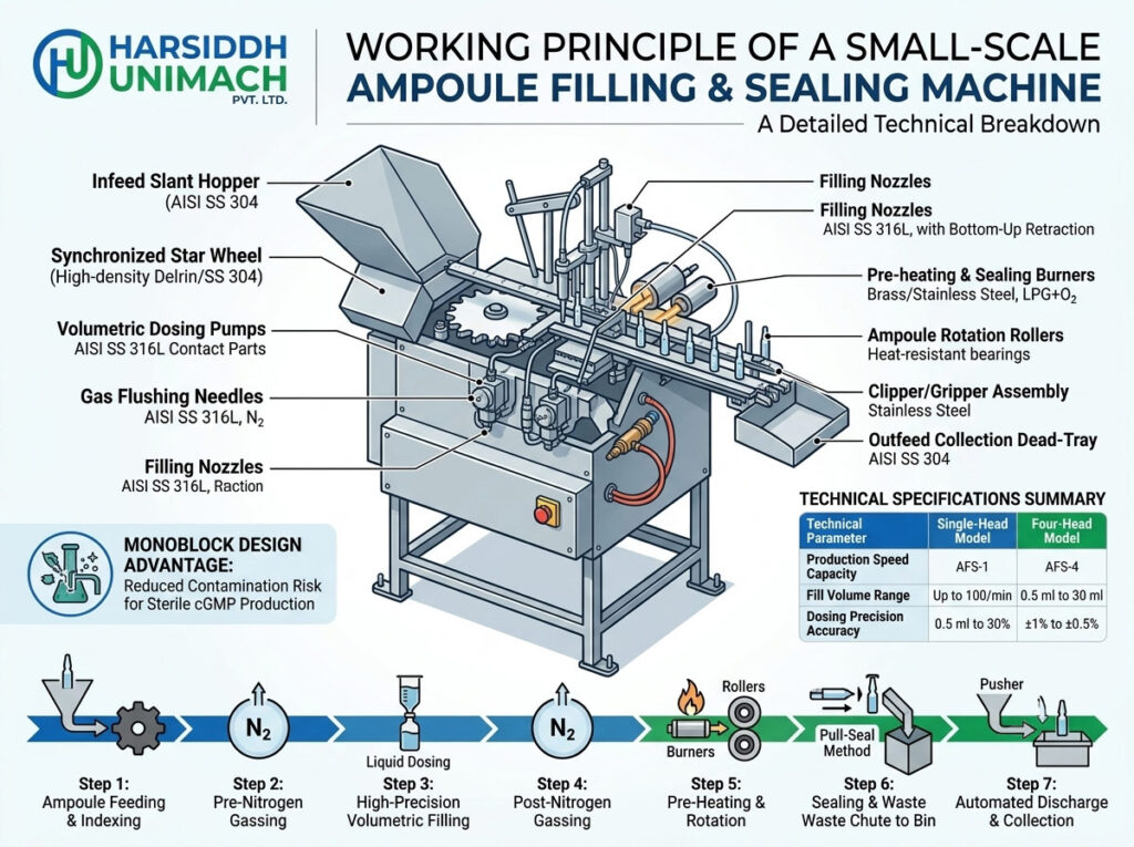
In the modern pharmaceutical, biotechnology, and cosmetic industries, protecting liquid formulations from atmospheric contamination, oxidation, and microbial degradation is paramount. Among the various packaging formats available, glass ampoules remain the gold standard for unit-dose parenteral drug delivery. These hermetically sealed containers guarantee product integrity and shelf-life.
For pharmaceutical manufacturing plants, laboratory environments, clinical trial batches, and small-scale production facilities, the Small-Scale Ampoule Filling and Sealing Machine is an indispensable piece of engineering.
As a premier pioneer in industrial packaging solutions, Harsiddh Unimach Pvt. Ltd. designs and manufactures state-of-the-art packaging equipment tailored to strict compliance requirements. This comprehensive guide provides an exhaustive breakdown of the working principle, mechanical architecture, operational phases, and technical advantages of a small-scale ampoule filling and sealing machine. Learn how this machinery optimizes sterile liquid filling lines.
Understanding the Small-Scale Ampoule Filling & Sealing Machine
An ampoule filling and sealing machine is a specialized industrial system designed to automate the precise dispensing of liquid products into open-mouth glass ampoules, followed immediately by an airtight flame-sealing process.
Unlike large-scale, multi-head rotary production lines that handle tens of thousands of ampoules per hour, a small-scale system—typically configured as a single-head, two-head, or four-head monoblock machine—is optimized for flexibility, rapid changeovers, and high accuracy for small to medium batches.
The Monoblock Design Advantage
Modern small-scale machines feature a monoblock arrangement. This means that both the filling and sealing operations are performed on a single, synchronized structural platform. Minimizing the time and physical distance between liquid exposure and final container closure dramatically reduces the risk of airborne contamination, ensuring complete sterility in compliance with current Good Manufacturing Practices (cGMP).
Core Structural Anatomy: Key Components
To fully grasp the working principle, it is essential to understand the mechanical components that work in tandem within a small-scale system manufactured by Harsiddh Unimach Pvt. Ltd.
| Component Name | Material Specification | Primary Functional Role |
| Infeed Slant Hopper | AISI SS 304 | Receives sterile, empty ampoules and feeds them sequentially via gravity. |
| Synchronized Star Wheel | High-density Delrin / SS 304 | Catches individual ampoules from the hopper and precisely indexes them onto the transport rack. |
| Slant-Travel Transport Rack | AISI SS 304 | Moves ampoules across functional stations at a 45-degree angle or step-by-step eccentric stroke. |
| Volumetric Dosing Pumps | AISI SS 316L (Contact parts) | High-precision piston or peristaltic pumps that draw and discharge exact liquid volumes. |
| Gas Flushing Needles | AISI SS 316L | Injects inert gas (typically Nitrogen) before and after liquid filling to displace oxygen. |
| Filling Nozzles | AISI SS 316L | Lowers into the ampoule neck to deposit liquid without touching the glass walls. |
| Pre-heating & Sealing Burners | Brass / Stainless Steel | Mixes LPG (Propane) and Oxygen to create high-temperature, adjustable pinpoint flames. |
| Ampoule Rotation Rollers | Heat-resistant bearings | Spins the ampoules continuously at the sealing station to ensure uniform heat distribution. |
| Clipper / Gripper Assembly | Stainless Steel | Pulls away the melted glass tip during the pull-sealing phase. |
| Outfeed Collection Dead-Tray | AISI SS 304 | Collects the filled and hermetically sealed ampoules in a safe, upright position. |
Detailed Step-by-Step Working Principle
The operating mechanism of a small-scale ampoule filling and sealing machine relies on a single main motor drive synchronized with a central eccentric cam system or servo-driven tracks. This mechanical synchronization ensures that every container progresses through the operational sequence with millisecond-level precision.
Step 1: Ampoule Feeding and Mechanical Indexing
The process begins with pre-sterilized, washed, and depyrogenated open-mouth glass ampoules (typically Type B or Type C open-funnel ampoules).
- The operator or an automated feed conveyor places the empty containers into the slant-travel infeed hopper.
- Due to the sloped architecture, the ampoules slide downward into a synchronized star wheel.
- The star wheel captures the ampoules individually or in pairs (depending on whether it is a single-head or two-head machine) and transfers them onto the eccentric moving transport rack.
- This transport rack advances the ampoules crosswise or vertically via a series of calculated mechanical strokes.
Step 2: Pre-Nitrogen Gassing (Oxygen Displacement)
Many pharmaceutical formulations—such as liquid vitamins, antibiotics, and biologics—are highly sensitive to oxidation. To prevent product degradation, the machine includes an integrated inert gas flushing mechanism.
- Once the transport rack positions the empty ampoules under the gassing manifold, a set of stainless steel gas needles descends into the ampoule necks.
- A controlled pulse of sterile Nitrogen gas (N₂) is injected, successfully displacing the atmospheric oxygen trapped inside the container.
Step 3: High-Precision Volumetric Liquid Filling
After the oxygen is evacuated, the rack moves the ampoules directly under the filling station.
- The machine utilizes a “No Ampoule – No Filling” sensor system. If a slot on the rack is empty due to a upstream feed break, the proximity sensor communicates with the PLC controller to deactivate that specific dosing pump stroke, preventing liquid wastage and machine contamination.
- When an ampoule is detected, the filling nozzles descend deep into the neck.
- The volumetric piston pumps (or servo-controlled peristaltic pumps) discharge a precise dose of liquid.
- To avoid “neck wetting”—where droplets cling to the inner walls of the upper neck and cause charring or black particles during the subsequent flame sealing phase—the filling nozzles are designed with a bottom-up retraction profiling mechanism. This mechanism centers the liquid stream perfectly down the core axis of the container.
Step 4: Post-Nitrogen Gassing
Immediately after the liquid is discharged, the ampoules advance to the post-gassing station.
- Another set of needles injects an additional layer of Nitrogen gas into the remaining headspace above the liquid level.
- This ensures that when the glass is melted shut, the product remains blanketed by an inert atmosphere, maximizing long-term stability and extending expiration shelf-life.
Step 5: Pre-Heating and Continuous Neck Rotation
Before final sealing can occur, the open glass neck must be conditioned to prevent thermal shock, cracking, or asymmetrical deformation.
- The filled ampoules advance to the pre-heating station, where they encounter lower-pressure gas flames generated by a mixture of Liquid Petroleum Gas (LPG) and Oxygen (O₂).
- At this exact position, the base of the ampoule settles against separate motorized rotation rollers.
- As the rollers spin, the ampoule rotates continuously on its vertical axis. This exposes the entire circumference of the glass neck to uniform, localized heat, softening the glass safely.
Step 6: Sealing and Waste Tip Removal
Once the glass neck reaches its optimal plasticization/melting temperature, it advances to the final sealing station.
There are two primary methods used to achieve a hermetic seal in small-scale systems:
A. The Tip-Sealing Method (Bead Sealing)
The machine applies a high-intensity, localized pinpoint flame directly to the top edge of the ampoule opening. As the container rotates, the glass melts downward due to surface tension, naturally fusing inward to form a rounded, smooth glass bead closure.
B. The Pull-Sealing Method (Standard Industrial Practice)
The high-intensity flame melts the center of the ampoule neck. Simultaneously, a mechanical clipper or gripper assembly descends, firmly grasps the waste top-funnel of the glass tip, and pulls it vertically upward.
As the glass is drawn apart, the molten material thins out, pinches closed, and fuses shut in the center. The waste glass tip is clipped off cleanly and ejected down a chute into a dedicated stainless steel waste collector bin, leaving behind a perfectly formed, hermetically sealed dome.
[Open Ampoule] ---> [Pre-Heating (Rotation)] ---> [Flame Fusion / Pull] ---> [Hermetic Seal]
Step 7: Automated Discharge and Collection
Following the sealing stroke, the transport rack carries the hot, freshly sealed ampoules to the exit zone. A smooth mechanical pusher arms or segment wheel transfers the finished containers onto an upright outfeed dead-tray collection magazine. Here, the ampoules cool down safely, maintaining an upright orientation to prevent any internal liquid contact with the still-setting hot glass domes, ready for downstream inspection, labeling, and cartoning.
Technical Specifications: What to Look For
When sourcing a small-scale ampoule filling and sealing system for R&D, clinical compounding, or boutique commercial production, mapping your operational parameters to engineering metrics is critical. Below is a representative technical data profile for small-scale models manufactured by Harsiddh Unimach Pvt. Ltd.
| Technical Parameter | Single-Head Model (AFS-1) | Two-Head Model (AFS-2) | Four-Head Model (AFS-4) |
| Production Speed Capacity | Up to 25 Ampoules/min | Up to 50 Ampoules/min | Up to 100 Ampoules/min |
| Fill Volume Range | 0.5 ml to 30 ml | 0.5 ml to 30 ml | 1 ml to 10 ml |
| Dosing Precision Accuracy | ±1% to ±0.5% | ±1% to ±0.5% | ±1% to ±0.5% |
| Required Combustible Gases | LPG + Oxygen (O₂) | LPG + Oxygen (O₂) | LPG + Oxygen (O₂) |
| Inert Gas Requirement | Nitrogen (N₂) | Nitrogen (N₂) | Nitrogen (N₂) |
| Electrical Power Input | 1 HP, 3-Phase, 415V | 1 HP, 3-Phase, 415V | 2 HP, 3-Phase, 415V |
| Contact Material Compliance | AISI SS 316L | AISI SS 316L | AISI SS 316L |
| Non-Contact Components | AISI SS 304 | AISI SS 304 | AISI SS 304 |
Crucial Advantages of Small-Scale Ampoule Systems
Investing in a high-quality small-scale machine offers distinct strategic advantages for modern pilot plants, laboratories, and specialized pharmaceutical manufacturers:
- Minimal Changeover Downtime: Small-scale machines are engineered with toolless format changeover capabilities. Switching the machine configurations between 1ml, 2ml, 5ml, or 10ml ampoules can be accomplished in minutes by adjusting the hand-wheels and swapping out format parts without complex tools.
- Exceptional Dosing Accuracy: Utilizing micro-bore volumetric syringe blocks or modern servo-driven peristaltic pump assemblies ensures that costly, high-value active pharmaceutical ingredients (APIs) are filled with tight tolerances, eliminating overfills and protecting profitability.
- Compact Footprint: These units are designed as compact benchtop or standalone monoblock modules, making them easy to integrate into limited cleanroom footprints, barrier isolation systems, or standard Laminar Air Flow (LAF) hoods.
- Low Media Consumption: The precision-regulated gas manifolds allow operators to fine-tune the exact consumption of LPG, Oxygen, and Nitrogen via flowmeters, minimizing waste during short production cycles.
Troubleshooting & Quality Assurance Checklist
To maintain seamless operation and maintain regulatory standards, production managers and line operators should monitor the following operational checkpoints:
1. Black Carbon Deposits or Charring
- Root Cause: Liquid product has splashed or dripped onto the inner wall of the ampoule neck during the filling cycle, or the filling nozzle is misaligned.
- Solution: Adjust the stroke height of the filling nozzle so it descends deeper into the ampoule before discharging. Ensure the “suck-back” setting on the dosing pump is calibrated correctly to prevent tail-end dripping.
2. Concave or Malformed Domes (Leakers)
- Root Cause: An imbalance in the ratio of LPG to Oxygen gas pressure, causing a flame that is either too cold (incomplete fusion) or too hot (over-melting and collapsing).
- Solution: Use the fine-tuning needle valves on the gas control panel to achieve a sharp, blue, pinpoint flame. Verify that the gas pressure regulators match the manufacturer’s recommended settings.
3. Glass Crackage or Thermal Shock
- Root Cause: The pre-heating station is skipped or running too cold, or the glass ampoules contain residual moisture from an incomplete drying cycle in the sterilization tunnel.
- Solution: Ensure the pre-heating burners are functional and positioned to warm the glass progressively before it reaches the intense sealing flames.
Why Choose Harsiddh Unimach Pvt. Ltd.?
In the pharmaceutical manufacturing sector, precision machinery dictates the safety and efficacy of the final therapeutic product. Harsiddh Unimach Pvt. Ltd. is an industry leader in the design, engineering, and distribution of premium-grade ampoule packaging solutions.
When you partner with Harsiddh Unimach, you leverage key engineering benefits:
- cGMP-Compliant Construction: All product contact tracks, dosing pumps, and gassing needles are crafted out of premium AISI SS 316L stainless steel, entirely free of crevices to ensure seamless Clean-in-Place (CIP) and Sterilize-in-Place (SIP) validation.
- Advanced Integration Capacities: Our small-scale machines can be equipped with PLC-based Human-Machine Interfaces (HMI), data-logging features compliant with 21 CFR Part 11, and integrated Class 100 Laminar Air Flow hoods.
- Global Footprint & Support: Operating out of Ahmedabad, India, we provide end-to-end technical documentation, DQ/IQ/OQ validation protocols, and rapid component provisioning to clients worldwide.
Explore our comprehensive catalog of liquid packaging technologies by visiting our official portal at www.harsiddhunimach.com.
Frequently Asked Questions (FAQs)
What is the difference between open-mouth and closed-mouth ampoules?
Open-mouth ampoules (Type B/C) are delivered with open tops and require gas flushing, liquid filling, and a flame pull-sealing step. Closed-mouth ampoules (Type D) arrive completely sealed from the glass manufacturer to prevent internal contamination during transit; the machine must first break or melt open the top before executing the standard filling and sealing cycle.
Can a single machine handle both glass and plastic ampoules?
Standard monoblock ampoule filling and sealing machines are engineered specifically for glass ampoules, utilizing LPG/Oxygen gas flames to fuse the glass material. Plastic ampoules require entirely separate Blow-Fill-Seal (BFS) technology or specialized thermal jaw heating elements rather than open gas burners.
Which filling pump type is best: Piston or Peristaltic?
Volumetric piston pumps offer durability and accuracy (±0.5%) for standard, non-corrosive liquid formulations. Peristaltic pumps are ideal for single-use bio-pharmaceutical workflows or highly corrosive fluids; the liquid only contacts the sterile silicone tubing, eliminating mechanical friction components and simplifying validation cleanups.
What gases are required for the sealing process?
The sealing station requires a mixture of a combustible fuel gas, such as Liquid Petroleum Gas (LPG), Natural Gas, or Propane, paired with pure Oxygen (O₂) to achieve temperatures capable of melting pharmaceutical-grade borosilicate glass cleanly.
Final Remarks
The automated working principle of a small-scale ampoule filling and sealing machine beautifully bridges the gap between mechanical precision and aseptic isolation. By understanding the synchronized progression from feeding, nitrogen blanketing, precise volumetric delivery, and targeted flame fusion, pharmaceutical operations can ensure zero product waste and robust quality assurance.
For customized technical consultations, product trials, or specific pricing regarding single-head or multi-head filling setups, contact our engineering experts today at Harsiddh Unimach Pvt. Ltd. via our website www.harsiddhunimach.com or submit your layout specifications directly to our engineering desk. Let us help you elevate your liquid packaging line with reliability, performance, and compliance.