
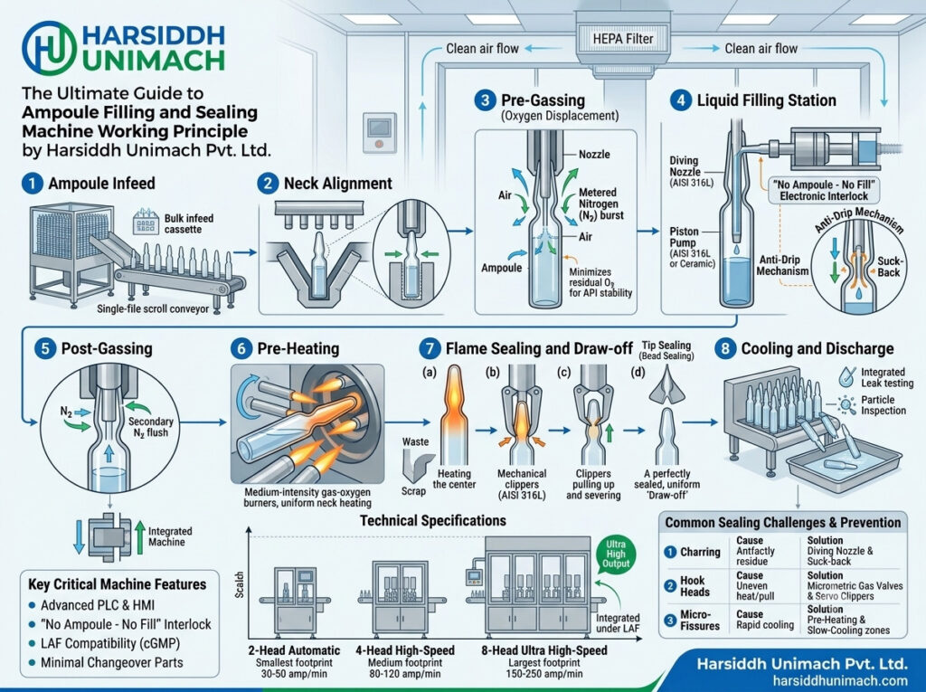
An ampoule filling and sealing machine performs a remarkable sequence of operations in just a few seconds: it moves fragile glass containers with precision, doses an exact volume of sterile liquid through a narrow neck, protects the product with inert gas, and then melts and closes the glass itself to create a hermetic seal. Every one of these actions must be perfectly synchronised — a few millimetres or milliseconds out of place, and the result is a wet neck, a charred tip, a leaking seal or a broken ampoule.
If you are new to ampoule filling, our introductory article on what an ampoule filling machine is and how it works is a good place to start. This guide goes deeper. We look inside the machine at the mechanisms that make each step possible, explain how the machine cycle is timed, describe the key settings that determine quality, and cover variations for closed ampoules, servo machines and different outputs.
The Core Working Principle in One Sentence
An ampoule filling and sealing machine indexes ampoules step by step through a series of stations — pre-gassing, filling, post-gassing, pre-heating and sealing — using a synchronised mechanical or servo drive, so that each ampoule receives an accurate dose and a uniform flame seal before being discharged.
Everything else is detail — but the detail is what separates a reliable machine from a troublesome one.
Main Functional Groups
To understand the working principle, it helps to divide the machine into five functional groups:
- Ampoule handling system – infeed, transport and outfeed.
- Dosing system – pumps, valves, tubing and needles.
- Gassing system – nitrogen supply, regulators and gassing needles.
- Sealing system – gas mixing, burners, ampoule rotation and pull-sealing tongs.
- Drive and control system – main drive, cams or servo motors, PLC and HMI.
For a labelled view of where these components sit, see our guide to understanding the ampoule filling machine diagram and working process.
1. The Ampoule Handling System
Infeed
Sterilised ampoules arrive at the infeed — either from trays loaded onto an inclined infeed hopper, or directly from a sterilising tunnel on an integrated line. The hopper is gently inclined so the ampoules roll forward under their own weight onto the transport system, while guides keep them upright and in order.
Transport mechanism
Most ampoule machines use a “walking beam” or rack-and-pinion transport. Ampoules rest in V-shaped grooves (serrated plates). A moving set of grooves lifts the ampoules, carries them forward by one pitch, and sets them down again, while the fixed grooves hold them in place during the next movement. This intermittent, step-by-step motion is driven by a cam or servo and moves all ampoules on the machine forward simultaneously.
The pitch of the grooves matches the ampoule diameter, which is why different ampoule sizes require different change parts. Correct alignment of the moving and fixed grooves is critical — any mismatch causes ampoules to tilt, chip or break.
Outfeed
After sealing, ampoules are transferred onto an outfeed tray where they cool gradually before inspection. Many machines include a rejection system for ampoules not filled due to missing containers or faults.
2. The Dosing System
Filling needles and the needle carriage
Filling needles are mounted on a carriage that moves vertically, synchronised with the transport. When the ampoules stop, the carriage lowers the needles into the ampoule necks. On modern machines, the needles enter deep into the ampoule and rise as the liquid is dispensed, keeping the needle tip just above the liquid surface. This reduces foaming and — most importantly — prevents liquid from splashing onto the neck, where it would char during sealing.
On many machines, the needle carriage also moves horizontally with the ampoules for a short distance — a “tracking” movement — to allow filling to continue during part of the transport cycle and increase output.
Dosing pumps
The number of pumps equals the number of filling heads. Three dosing principles are common:
- Syringe (piston) pumps: a glass or stainless steel syringe draws liquid from the supply line and discharges it through the needle, controlled by non-return valves. Volume is set by adjusting the piston stroke. This is the traditional and most widely used design.
- Servo-driven pumps: a servo motor drives the pistons, so volume, fill speed and suck-back are set digitally from the HMI. Learn more in servo technology in modern ampoule filling machines.
- Peristaltic pumps: rollers compress a tube to push liquid forward. The product only touches the tube, which is ideal for sensitive or high-value products. See the Automatic Peristaltic Based Ampoule Filling Machine.
Different products and plants also use gravity or vacuum-assisted filling approaches; our article on vacuum filling vs gravity filling in ampoule machines compares these methods in detail.
Drip prevention
At the end of each dose, a small reverse movement of the pump — called suck-back — draws the last drop back into the needle. This keeps the neck dry as the needle withdraws.
3. The Gassing System
For oxygen-sensitive products, inert gas — usually nitrogen — is introduced at two points:
- Pre-gassing: before filling, a gassing needle enters the ampoule and flushes it with nitrogen, displacing air.
- Post-gassing: after filling, nitrogen fills the headspace above the liquid until the moment of sealing.
Gas flow is controlled by pressure regulators, flow meters and solenoid valves timed to the machine cycle. Gas is passed through sterile-grade filters before entering the ampoules. Too little flow leaves oxygen behind; too much can splash product onto the neck or disturb the sealing flame.
4. The Sealing System
The sealing station is the most critical part of the machine.
Gas mixing and burners
Burners use a mixture of fuel gas (LPG or natural gas) and oxygen. The ratio is controlled through regulators and flow meters, and the mixed gas is delivered to a series of burner nozzles. A correct ratio produces a stable, hot, blue flame with sharp cones; too much fuel produces a yellow, sooty flame that deposits carbon, while too much oxygen produces a harsh, noisy flame that can overheat the glass.
Burners are usually arranged in two zones:
- Pre-heating burners gently warm the ampoule neck to reduce thermal shock.
- Sealing burners heat the neck to its softening point for sealing.
Ampoule rotation
While in the sealing zone, ampoules are rotated continuously by rollers. Rotation ensures that the neck is heated evenly all round, producing a symmetrical seal without thin spots. Rotation speed must be matched to flame intensity and dwell time.
Pull sealing
When the neck is soft, a pair of tongs (or a collet) grips the tip of the ampoule and pulls it upward. The soft glass stretches and separates, and the flame closes the remaining neck into a smooth, rounded tip. The excess glass tip is discarded.
Pull sealing produces a stronger, more uniform and more reliable seal than simple tip (fusion) sealing, where the top of the neck is just melted closed. For this reason, pull sealing is the preferred method for pharmaceutical injectables.
5. The Drive and Control System
Mechanical (cam-driven) machines
In traditional machines, a single main motor drives a camshaft. Each cam controls one motion — ampoule transport, needle carriage up/down, pump stroke, tong movement — so all actions are mechanically synchronised. These machines are robust and proven, though changes require mechanical adjustment.
Servo-driven machines
In modern machines, separate servo motors drive key motions, coordinated electronically by a motion controller or PLC. This allows fill volume, needle profile, fill speed and timing to be stored in recipes and changed from the HMI. Changeovers are faster, and settings are more repeatable.
Safety interlocks
Typical interlocks include no-ampoule-no-fill sensors, flame failure detection, gas pressure monitoring, guard door switches and emergency stops. These protect product, equipment and operators.
The Machine Cycle Step by Step
Putting it all together, one complete machine cycle looks like this:
- The transport mechanism indexes all ampoules forward by one pitch.
- Sensors confirm ampoules are present at each filling position.
- Gassing needles enter and pre-gas the ampoules.
- Filling needles dive into the ampoules and the pumps dispense the dose while the needles rise.
- Suck-back prevents drips as the needles withdraw.
- Post-gassing flushes the headspace.
- Ampoules move into the pre-heating zone and start rotating.
- Sealing burners soften the neck; tongs pull the tip away to seal.
- Sealed ampoules move to the outfeed tray to cool.
At any moment, several groups of ampoules are at different stages, so the machine performs gassing, filling and sealing simultaneously on different ampoules.
How Closed Ampoules Are Processed
Closed ampoules arrive sealed from the glass manufacturer, protecting their interior until filling. Machines designed for them add a tip-opening station before filling: the tip is heated and scored or cut so it can be removed cleanly, and any glass fragments are extracted by suction. The ampoule is then filled and resealed in the usual way. See our four head closed ampoule filling and sealing machine and the full range of ampoule filling machines for closed ampoules, alongside our ampoule filling machines for open ampoules.
Variations by Number of Heads
The same working principle applies across machine sizes; the number of heads determines output:
- Single head – laboratory and pilot batches: single head ampoule filling and sealing machine.
- Two head – small production: two head ampoule filling and sealing machine.
- Four head – medium production: Automatic Four Head Ampoule Filling & Sealing Machine.
- Six head – higher production: six head ampoule filling and sealing machine.
- Eight head – high-volume commercial production: high-speed eight head vertical ampoule filling and sealing machine.
Specialised machines also exist for formats such as crushable ampoules — see the Automatic Crushable Ampoule Filling and Sealing Machine. Browse our complete ampoule filling machine category.
Key Settings That Determine Quality
| Setting | Effect if Wrong | What Good Looks Like |
|---|---|---|
| Fill volume | Under- or overfilling | Within specified tolerance, verified by weight checks |
| Needle depth and rise | Foaming, splashing, wet neck | Smooth bottom-up fill, dry neck |
| Suck-back | Drips on neck and charred tips | No visible droplet at needle tip |
| Nitrogen flow | Residual oxygen or splashing | Steady, gentle flow timed with cycle |
| Gas/oxygen ratio | Sooty or overheated seals | Stable blue flame with sharp cones |
| Burner position | Uneven or off-centre seals | Flame focused on the neck constriction |
| Rotation speed | Thin spots, uneven seals | Uniform heating all round |
| Pull timing | Capillaries, long tips, bulbs | Smooth, rounded, uniform tips |
Upstream and Downstream Integration
The ampoule filling and sealing machine depends on clean, sterile ampoules from upstream equipment such as a rotary ampoule washing machine and a sterilising tunnel. After sealing, ampoules are leak tested, visually inspected and labelled — for example, on a horizontal ampoule sticker labelling machine.
Keeping the Machine at Its Best
Consistent sealing and dosing depend on regular care: cleaning burner nozzles, checking syringe and valve seals, inspecting transport grooves and tongs, verifying gas regulators and calibrating fill volumes. Our ampoule filling machine maintenance checklist lists the critical components to inspect regularly.
Frequently Asked Questions
What is the working principle of an ampoule filling and sealing machine? It indexes ampoules through gassing, filling, post-gassing, pre-heating and sealing stations using a synchronised drive, so each ampoule is accurately filled and flame-sealed.
Why is pull sealing preferred? Pull sealing stretches and separates the softened neck, producing a stronger, more uniform seal with fewer capillaries than tip sealing.
What gases are used for ampoule sealing? A mixture of fuel gas, such as LPG or natural gas, with oxygen. Nitrogen is used separately for purging oxygen-sensitive products.
What causes charred ampoule tips? Usually liquid on the neck from splashing, dripping or foaming, which burns during sealing. Correct needle movement and suck-back prevent it.
How are closed ampoules filled? The machine opens the tip by heating and cutting it, removes glass fragments by suction, fills the ampoule and then reseals it.
Looking for an ampoule filling and sealing machine built for consistent seals? Contact our team or send an inquiry to discuss your requirements.