
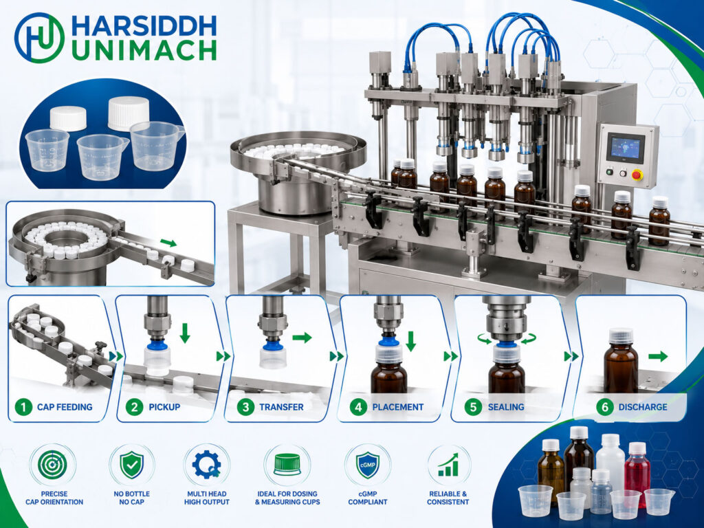
Not every cap can simply be picked off a chute by a passing bottle. Tall caps, pumps, trigger sprayers, flip-top closures, child-resistant caps and caps with unusual shapes need to be handled more carefully — placed squarely on the bottle neck and then tightened to a precise torque. For these closures, and for any application where placement accuracy and torque control matter most, manufacturers turn to the pick and place capping machine.
As the name suggests, a pick and place capper uses a gripping head to pick a cap from a feed point and place it accurately onto the bottle, usually tightening it at the same time. This controlled handling reduces cross-threading, tilted caps and inconsistent torque, and makes it possible to cap a much wider range of closures.
In this article, we explain how pick and place capping machines work, the main machine designs, the closures they handle best, the settings that determine capping quality and how to troubleshoot common problems. For an overview of all capping methods, see our guide to the bottle capping machine working principle.
What Makes Pick and Place Different?
In a standard pick-off system, the bottle neck catches the leading cap at the end of a chute and carries it away, with the cap resting loosely before being tightened. This works well for simple, low-profile caps but can cause problems with tall, heavy or irregular closures, which may tilt or fall.
In a pick and place system:
- The cap is gripped securely by a capping head before it ever touches the bottle
- The head positions the cap precisely over the bottle neck
- The cap is lowered and threaded on in a controlled motion
- Torque is applied by the same head until the set value is reached
This control over the cap from start to finish is what makes pick and place capping so versatile.
The Core Working Principle
A pick and place capper performs four steps for every bottle:
- Feed — caps are oriented and delivered to a pick-up station
- Pick — a capping head grips one cap
- Place — the head lowers the cap onto the bottle neck, aligned and square
- Tighten — the head rotates the cap to the required torque, then releases it
Main Components
- Cap hopper and feeder — vibratory bowl, elevator or sorter that orients caps
- Cap chute and pick-up station — presents one cap at a time in a fixed position
- Bottle infeed system — conveyor, infeed worm and star wheel to space and position bottles
- Capping heads — each with a gripping chuck or collet and a torque-limiting mechanism
- Vertical motion system — cam track or servo that raises and lowers the heads
- Rotation drive — spins the heads to tighten caps
- Bottle hold-down or neck support — prevents bottles from rotating during tightening
- Outfeed star wheel and conveyor — discharges capped bottles
- Control system — speed control, sensors and safety interlocks
Step-by-Step Working Process
Step 1: Cap feeding and orientation
Caps are loaded into a hopper. A feeder orients them consistently — for screw caps, open side down; for pumps and triggers, in a specific orientation using dedicated tooling. Oriented caps move down a chute to the pick-up station.
Step 2: Bottle infeed
Filled bottles arrive from the filler — for example, our cosmetic bottle filling machine or lotion and gel filling machine. An infeed worm separates them and a star wheel transfers each bottle into position beneath a capping head.
Step 3: Cap pick-up
As the turret rotates (on rotary machines), each capping head passes over the pick-up station. The head lowers, its chuck or collet grips the cap, and the head rises again with the cap held firmly.
Step 4: Cap placement
The head carries the cap to the bottle position. A cam track or servo lowers the head so that the cap meets the bottle neck squarely. Bottle neck supports or star wheel pockets keep the bottle steady and centred.
Step 5: Tightening to torque
The head rotates, threading the cap onto the bottle. A torque-limiting device — magnetic clutch, mechanical clutch or servo torque control — slips or stops once the set torque is reached. This ensures every cap is tightened consistently without over-tightening.
Step 6: Release and discharge
The chuck opens to release the cap, the head rises and the bottle is transferred to the outfeed conveyor.
Types of Pick and Place Capping Machines
Rotary multi-head pick and place cappers
The most common design for production lines. Several capping heads — typically four, six or eight — are mounted on a rotating turret. Heads pick, place and tighten caps continuously as the turret turns.
- Automatic Four Head Pick and Place Type Screw Capping Machine — medium output
- Automatic Six Head Pick and Place Type Screw Capping Machine — higher output
- Automatic Eight Head Pick and Place Type Screw Capping Machine — high-speed lines
Single head pick and place cappers
A single head handles one bottle at a time, often used for lower output, large containers or special closures.
Servo-driven pick and place cappers
Servo motors control vertical motion and rotation precisely. Torque, speed and thread-engagement profiles can be programmed and stored as recipes, making these machines highly repeatable and quick to change over.
Robotic and gantry systems
For very unusual closures or large containers, robotic arms or gantry systems may pick and place caps, although these are less common in standard pharmaceutical lines.
Closures Best Suited to Pick and Place Capping
- Screw caps where precise torque control is important
- Tall or heavy caps that tilt with pick-off systems
- Pumps and dispensers for lotions, soaps and sanitisers
- Trigger sprayers for cleaning products
- Flip-top and dispensing caps
- Child-resistant closures
- Sports caps and special-shaped closures
- Jar lids on wide-mouth containers — see the Automatic Jar Capping Machine
Pick and Place vs Other Capping Methods
| Feature | Pick and Place | Pick-Off with Chuck | Spindle (Inline) Capper |
|---|---|---|---|
| Cap control | Gripped from start to finish | Cap rests loosely before tightening | Cap rests loosely, tightened by spinning discs |
| Placement accuracy | Very high | Good | Moderate |
| Torque control | Precise, per head | Good | Moderate |
| Suitable closures | Wide range, incl. pumps and triggers | Simple screw caps | Simple screw caps |
| Speed | Medium to high (rotary) | Medium to high | Medium |
| Changeover | Moderate | Moderate | Quick |
| Typical use | Pharma, cosmetics, special closures | General bottling | Flexible lines, many bottle shapes |
For comparison, see our linear capping machine, and read the bottle screw capping machine working principle for more on standard screw capping.
Why Torque Control Matters
Torque determines how tightly a cap is applied:
- Too low: leaks, loosening during transport and contamination risk
- Too high: caps that are hard to open, stripped threads and damaged liners
Pick and place cappers apply torque through each head’s clutch or servo drive. Application torque is verified regularly with a torque tester, and removal torque — the force needed to open the cap — is also checked, since it can change after induction sealing or storage.
Key Settings and Their Effects
| Setting | Effect if Incorrect |
|---|---|
| Chuck or collet size | Caps not gripped or damaged |
| Pick-up height and timing | Caps missed or picked at an angle |
| Placement height | Cross-threading or insufficient engagement |
| Torque setting | Loose or over-tight caps |
| Rotation speed | Incomplete threading or cap damage |
| Bottle hold-down pressure | Bottles rotate or deform |
| Conveyor and star wheel timing | Bottles mispositioned under heads |
Where Pick and Place Capping Fits in the Line
- Bottle unscrambling
- Bottle cleaning
- Filling
- Pick and place capping
- Induction sealing — on an induction sealing machine
- Labelling — for example, with a bottle sticker labeling machine
- Cartoning and packing
Troubleshooting Common Problems
| Problem | Likely Cause | Solution |
|---|---|---|
| Caps not picked up | Wrong pick-up height, worn chuck, chute misaligned | Adjust height, replace chuck, align chute |
| Cross-threaded caps | Cap placed at an angle, bottle not centred | Adjust placement height, check neck support |
| Loose caps | Low torque setting, worn clutch | Increase torque, service clutch |
| Over-tight caps | High torque setting | Reduce torque, verify with tester |
| Scratched or damaged caps | Wrong chuck inserts, excessive grip | Fit correct inserts, adjust grip |
| Bottles spinning | Insufficient hold-down | Increase hold-down, check supports |
| Variation between heads | One head’s clutch or chuck worn | Inspect and adjust each head |
Maintenance Tips
- Inspect chucks and inserts for wear; replace them before they slip or mark caps
- Check and calibrate torque clutches regularly
- Clean cap feeders and chutes to prevent jams
- Inspect cam tracks, bearings and drive components
- Verify bottle supports and star wheels for wear
- Keep change parts for each cap and bottle size labelled and organised
- On multi-head machines, check torque head by head
Changeover Between Cap and Bottle Sizes
Because a pick and place capper grips every cap, the parts that touch the cap and the bottle must match each format. A typical changeover involves:
- Chucks or collet inserts — swapped to suit the new cap diameter and profile
- Cap feeder tooling — bowl tooling, chute guides and the pick-up station adjusted or replaced
- Infeed worm and star wheels — changed to match the new bottle diameter
- Bottle neck supports and hold-downs — reset for the new bottle height and shape
- Head height — adjusted so that pick-up and placement happen at the correct points
- Torque setting — set to the value specified for the new closure and checked with a torque tester
On servo-driven machines, many of these values are stored as recipes, so heights, speeds and torque profiles can be recalled rather than set by hand. Labelled, colour-coded change parts and a written changeover checklist help operators complete the job consistently and reduce start-up rejects.
Pick and Place Capping in Pharmaceutical Production
In pharmaceutical plants, capping is a critical step for product protection, so pick and place cappers are usually expected to offer:
- Contact parts in suitable stainless steel or approved materials that are easy to clean
- Cap presence and high-cap detection, with automatic rejection of faulty bottles
- No bottle, no cap logic so caps are not wasted or dropped on the machine
- Torque verification recorded during start-up and at defined intervals
- Documentation that supports installation and operational qualification
Removal torque and seal integrity are typically included in in-process checks, particularly where caps are followed by induction sealing. Always confirm your exact requirements against your own quality procedures and the current applicable guidelines.
Choosing a Pick and Place Capping Machine
- Closure types — screw caps, pumps, triggers or special closures
- Bottle types — glass or plastic, round or shaped
- Output — single head or four, six or eight head rotary
- Torque requirements and control method (clutch or servo)
- Changeover frequency
- Line integration with filler and downstream equipment
- GMP requirements for pharmaceutical products
For a broader selection guide, read choosing the right capping machine for your pharmaceutical production line and cap sealing machine: choose the right sealing solution. Explore our capping machines, the capping machine for glass and PET bottles range, our bottle screw and ROPP capping machine, the semi-automatic screw capping machine for small batches and all capping machines on Harsiddh Engineering.
Frequently Asked Questions
What is a pick and place capping machine? A capping machine that grips each cap with a capping head, places it accurately on the bottle and tightens it to a set torque.
How is it different from a pick-off capper? In pick-off systems, the bottle collects the cap from a chute and the cap rests loosely before tightening. Pick and place cappers control the cap from pick-up to final torque.
Which closures need pick and place capping? Tall caps, pumps, trigger sprayers, flip-top and child-resistant closures and any caps that tilt or fall with pick-off systems.
How is torque controlled? Through magnetic or mechanical clutches, or servo drives, in each capping head, verified regularly with a torque tester.
What causes cross-threaded caps? Usually caps placed at an angle, bottles not centred under the head or incorrect placement height.
Need a pick and place capping machine for your closures? Contact our team or send an inquiry to discuss your bottles and caps.