
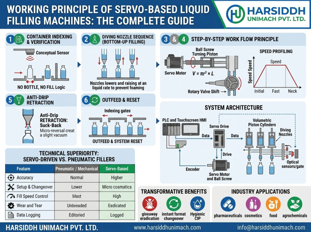
Working Principle of Servo Based Liquid Filling Machines
Servo based liquid filling machines are known for accuracy, repeatability and quick changeovers. But what actually happens inside the machine to make that possible? How does a motor know exactly how far to move? How is rotation turned into a precise volume of liquid? And how do nozzles, pumps and conveyors stay perfectly in step?
This article answers those questions from an engineering perspective. We explain the components of a servo system, how closed-loop control works, how servo motion is converted into a measured dose for different pump types, how nozzle movement and fill profiles are controlled, and how the whole machine is synchronised. If you are looking for a buyer-focused overview of types, benefits and applications, see our companion article: servo based liquid filling machines explained.
The Core Idea
A servo based liquid filling machine converts precisely controlled motor movement into a precisely measured volume of liquid. The servo system ensures that the motor moves exactly as commanded — the right distance, at the right speed, at the right time — on every cycle. Because the dosing mechanism links motor movement directly to delivered volume, controlling the motor means controlling the dose.
The Building Blocks of a Servo System
1. Servo motor
A servo motor — typically a brushless AC permanent-magnet motor — is designed for precise control of position, speed and torque. It can accelerate, decelerate, stop and reverse quickly and smoothly.
2. Encoder (feedback device)
Mounted on the motor shaft, the encoder measures the motor’s actual position continuously, often with very high resolution per revolution. This feedback is the key difference between a servo and an ordinary motor.
3. Servo drive (amplifier)
The drive supplies power to the motor and runs the control loops. It compares the commanded position with the encoder’s actual position and adjusts the motor current to eliminate any difference.
4. Motion controller or PLC
The controller generates motion commands — how far, how fast and when each axis should move — and coordinates multiple servo axes and machine functions.
5. HMI (touchscreen)
The operator interface where fill volumes, speeds, profiles and recipes are entered and stored, and where alarms and production data are displayed.
How Closed-Loop Control Works
Servo drives typically use three nested control loops:
- Position loop – compares commanded and actual position and generates a speed command to correct any error.
- Velocity loop – compares commanded and actual speed and generates a torque (current) command.
- Current (torque) loop – controls the electrical current in the motor windings to produce the required torque.
These loops run continuously at high speed. If the load changes — for example, because a thicker product resists the piston more — the drive detects the tiny deviation and increases torque to keep the motion on track. The difference between commanded and actual position, called following error, is kept extremely small. If it grows beyond a set limit, the drive raises an alarm, which helps detect jams or mechanical problems.
This is why servo fillers deliver consistent doses even when conditions vary slightly: the system corrects itself many times during every single fill.
Converting Motor Movement Into Dose Volume
The servo motor rotates, but the dose is a volume of liquid. The link between the two depends on the dosing mechanism.
Servo piston dosing
In a servo piston filler, the motor’s rotation is converted into linear motion, usually through a ball screw or a crank mechanism. The piston moves inside a precision cylinder:
- Suction stroke: the piston retracts, drawing product into the cylinder through an inlet valve.
- Delivery stroke: the valve switches and the piston moves forward, pushing product through the nozzle.
The delivered volume equals the piston’s cross-sectional area multiplied by the stroke length. Because the controller knows exactly how many encoder counts correspond to each millimetre of piston travel, it can set the stroke — and therefore the volume — with high resolution. Entering “100 ml” on the HMI simply tells the controller how far to move the piston.
See the Automatic Servo Based Piston Filling Machine and our servo based piston filling machine.
Servo gear pump dosing
In a gear pump filler, each revolution of the pump moves a known volume of liquid trapped between the gear teeth and the housing. The servo motor turns the pump a precise number of revolutions — including fractions of a revolution — to deliver the target volume. Smooth acceleration and deceleration reduce pulsation and splashing.
See the Automatic Servo Based Gear Pump Filling Machine, our servo based gear pump filling machine and our servo based oil and viscous filling machine.
Servo peristaltic dosing
In a peristaltic filler, rollers on a rotor squeeze a flexible tube. Each rotation pushes forward a volume determined by the tube’s internal diameter and roller geometry. The servo controls the rotor angle precisely, so the dose is proportional to the angle turned. Because tubing properties can change with wear, peristaltic systems are recalibrated regularly. See our peristaltic based liquid filling machine.
Calibration and per-nozzle offsets
In practice, the theoretical volume per stroke or revolution is refined through calibration. The operator fills sample containers, weighs them and enters a correction factor. On multi-nozzle machines, each nozzle can have its own offset so that all heads deliver the same dose despite tiny differences between pumps.
Controlling the Fill Profile
Servo control allows not just how much product is delivered, but how it is delivered.
Speed profiles
A typical fill profile has three phases:
- Slow start – reduces splashing as liquid first hits the container base.
- Fast main fill – delivers most of the volume quickly.
- Slow finish – reduces turbulence and foaming as the container nears full.
The controller shapes this profile by commanding different speeds over different portions of the stroke or rotation.
Suck-back
At the end of the dose, the servo briefly reverses — pulling the piston back slightly or turning the pump backwards — to draw the last drop back into the nozzle. This prevents drips on the container neck and conveyor.
Pressure and viscosity considerations
For thick products, slower fill speeds prevent excessive pressure in the product path; for thin products, faster fills are possible. Recipes store the appropriate profile for each product.
Controlling Nozzle Movement
Many servo fillers use an additional servo axis to move the nozzle carriage vertically.
- Diving: the nozzles descend close to the bottom of the container before filling starts.
- Rising with the liquid: as the container fills, the nozzles rise at a speed matched to the rising liquid level, keeping the tip just below or at the surface.
- Withdrawal: after suck-back, the nozzles rise clear of the container.
Coordinating the nozzle axis with the dosing axis is what makes true bottom-up filling possible, minimising foaming for products such as shampoos, detergents and syrups.
Synchronising the Whole Machine
A filling machine is a coordinated system. A typical inline servo filler’s cycle looks like this:
- Bottles arrive on the conveyor, often fed by a bottle unscrambler.
- Sensors count bottles and confirm they are in position; stopper gates hold them under the nozzles.
- Nozzle axis dives into the bottles.
- Dosing axes deliver the programmed fill profile while the nozzles rise.
- Suck-back prevents dripping, and the nozzles withdraw.
- Gates open and filled bottles move on to capping, for example on a bottle screw and ROPP capping machine.
The controller manages the timing of every step. In more advanced designs — such as rotary machines or monoblocks — servo axes are linked through electronic gearing or camming, so dosing and nozzle motion follow the container position continuously. See our liquid bottle filling and capping machine (monoblock).
Safety and quality interlocks
- No-bottle-no-fill: a nozzle only doses if a container is detected beneath it.
- Bottle jam detection: stops the conveyor and dosing if containers back up.
- Low tank level: pauses filling if the product supply runs low.
- Following error alarms: stop the machine if a servo axis cannot follow its commanded motion.
- Guard interlocks and emergency stops protect operators.
Recipes: Storing the Working Parameters
A recipe stores all the settings for one product and container combination:
- Target volume and calibration factors
- Per-nozzle offsets
- Fill speed profile
- Suck-back distance
- Nozzle dive depth and rise speed
- Conveyor speed and gate timing
Selecting a recipe instantly configures every servo axis, which is why changeovers on servo fillers are so much faster than on mechanical machines.
Closed-Loop Dose Correction
Some lines add a check-weigher downstream of the filler. Filled containers are weighed automatically, and if the average weight from a particular nozzle drifts, the controller adjusts that nozzle’s dose. This extends closed-loop control from motor position all the way to the final product weight. For context on how accuracy is defined and monitored, see filling machine accuracy standards in pharma manufacturing.
Mechanical vs Servo: Why the Principle Matters
| Aspect | Mechanical / Pneumatic | Servo |
|---|---|---|
| How the dose is set | Physical stops, screws or cams | Programmed motor movement |
| Correction for load changes | None | Continuous closed-loop correction |
| Fill profile | Fixed | Programmable |
| Nozzle motion | Fixed stroke | Programmable dive and rise |
| Changeover | Manual adjustment | Recipe selection |
| Diagnostics | Limited | Following error, torque and alarm data |
For a broader view of filling principles beyond servo, read liquid filling machine working principle explained. The same servo principles also apply to injectable filling, as described in servo technology in modern ampoule filling machines.
Applying the Principle: A Syrup Filling Example
Consider a pharmaceutical syrup line filling 100 ml bottles on a multi-nozzle servo piston filler:
- The operator selects the “Syrup 100 ml” recipe.
- The controller sets the piston stroke for 100 ml, applies the stored calibration factor and per-nozzle offsets, and loads the fill profile.
- As bottles are positioned, the nozzles dive to the bottle base.
- The pistons deliver a slow-fast-slow stroke while the nozzles rise with the liquid level.
- A short reverse stroke provides suck-back, and the nozzles withdraw.
- Bottles move on to capping and measuring-cup placement.
- Every few minutes, sample bottles are weighed; if a nozzle drifts, its offset is adjusted on the HMI.
For more on this application, see the automatic liquid syrup filling machine working principle and our bottle filling machines for oral liquids.
Factors That Still Affect Accuracy
Even with servo control, accuracy depends on:
- Air in the product path – air compresses, so the same piston stroke delivers less liquid
- Seal and valve wear – leakage past seals reduces delivered volume
- Product temperature – affects viscosity and density
- Tubing wear in peristaltic systems
- Supply conditions – stable tank level and pressure help consistency
Good priming, preventive maintenance and regular verification keep a servo filler performing at its best.
Maintenance From an Engineering Perspective
- Keep servo motors and drives clean and well ventilated
- Inspect cables and connectors on moving axes for wear
- Monitor following error and torque trends — rising values may indicate mechanical wear
- Lubricate ball screws and guides as specified
- Replace piston seals, gear pump parts or peristaltic tubing on schedule
- Back up PLC programs, drive parameters and recipes
Frequently Asked Questions
What is the working principle of a servo based liquid filling machine? It converts precisely controlled servo motor movement into a precise volume of liquid through a piston, gear pump or peristaltic mechanism, with closed-loop feedback ensuring every movement is accurate.
How does the machine know how far to move the piston? The controller converts the target volume into a piston stroke using the cylinder dimensions and calibration factors, and the encoder confirms the actual position.
What is following error? The difference between the commanded and actual position of a servo axis. Servo drives keep it very small and raise an alarm if it exceeds a limit.
Why do servo fillers use suck-back? A brief reverse movement at the end of each dose draws the last drop back into the nozzle, preventing drips.
Can servo fillers correct their own dose? Yes, when linked to a check-weigher, the controller can adjust individual nozzle doses automatically based on measured weights.
Want to see servo filling technology in action? Explore our liquid filling machines, the Automatic Servo Based Liquid Filling Machine and our liquid filling machines on Harsiddh Engineering, contact our team or send an inquiry.